System Planning
System Planning Forms and Guidelines
DBS-2.3/9.2-540
T1 Networking - Revised April 2000
Page 15
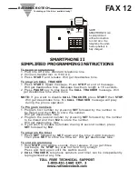
Network Trunk Configuration and Trunk Routing
Determine the network call traffic between the DBS nodes and the number of
trunks required to handle this traffic. Note that calls can be relayed through
another network DBS to reduce cost or simplify connections.
Diagram the trunking on the following diagram by
filling in the dashed lines
for actual trunk connections with a solid line
.
Figure 2-3. Network Trunking Configuration
Each set of network trunks connecting to another DBS must be placed into a
Network Trunk Group that will be used for network call routing purposes. Up
DBS 1
DBS 2
DBS 4
DBS 3
1XXX
2XXX
4XXX
3XXX
No. of Trunks _____
No. of
Trunks _____
No. of
Trunks _____
No. of Trunks _____
No. of Trunks _____
No. of Trunks _____
Summary of Contents for DBS Section 540
Page 6: ...Page 6 T1 Networking Revised April 2000 DBS 2 3 9 2 540 ...
Page 12: ...Page 12 T1 Networking Revised April 2000 DBS 2 3 9 2 540 ...
Page 62: ...Page 62 T1 Networking Revised April 2000 DBS 2 3 9 2 540 ...
Page 80: ...Page 80 T1 Networking Revised April 2000 DBS 2 3 9 2 540 ...
Page 127: ...Network Feature Operation SMDR DBS 2 3 9 2 540 T1 Networking Revised April 2000 Page 127 ...
Page 128: ...SMDR Network Feature Operation Page 128 T1 Networking Revised April 2000 DBS 2 3 9 2 540 ...
Page 146: ...146 T1 Networking Revised April 2000 DBS 2 3 9 2 540 Index ...