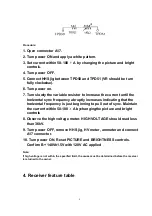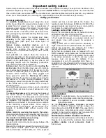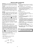
Procedure:
1. Open connector A17.
2. Turn power ON and apply a white pattern.
3. Set current within 50-100 A by changing the picture and bright
controls.
4. Turn power OFF.
5. Connect HHS jig between TPD50 and TPD51 (VR should be turn
fully clockwise).
6. Turn power on.
7. Turn slowly the variable resistor to increase the current until the
horizontal sync frequency abruptly increases indicating that the
horizontal frequency is just beginning to pull out of sync. Maintain
the current within 50-100 A bychangingthe picture and bright
controls
8. Observe the high voltage meter. HIGH VOLTAGE should read less
than 36kV.
9. Turn power OFF, remove HHS jig, HV meter, ammeter and connect
A17 connector.
10. Turn power ON. Reset PICTURE and BRIGHTNESS controls.
Confirm B+ 140V±1.5V with 120V AC applied
Note:
If high voltage is not within the specified limit, the cause must be determined before the receiver
is returned to the owner.
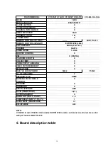
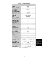
4. Receiver feature table
9
Summary of Contents for CT-32SC13-1G
Page 63: ... 50 A Board ...
Page 65: ... 52 ERJ6GEYJ183V NP2AH037AC ERENCES A Board ...
Page 66: ... 53 A Board ...
Page 69: ... 56 D Board ...
Page 70: ... 57 D Board ...
Page 71: ... 58 D Board ...
Page 74: ... 61 notes NOTES ...
Page 75: ... 62 G Board ...
Page 76: ... 63 G Board ...
Page 77: ... 64 G Board ...
Page 79: ... 66 L Board ...
Page 80: ... 67 L Board ...
Page 81: ... 68 A PCB ...
Page 82: ... 69 A PCB ...
Page 83: ... 70 D PCB ...
Page 84: ... 71 D PCB ...
Page 85: ... 72 G PCB ...
Page 86: ... 73 G PCB ...
Page 87: ... 74 L PCB ...
Page 88: ... 75 notes NOTES ...


