terminals, control shafts, etc. If the exposed metallic part has a returnpathto the chassis, the
reading should be between 240k and 5.2M . If the exposed metallic part does not have a
return path to the chassis, the reading should be infinite.
1.3. Leakage current hot check
Plug the AC cord directly into the AC outlet. Do not use an isolation transformer during the check.
Connect a 1.5k 10 watt resistor in parallel with a 0.15
F capacitor between an exposed
metallic part and ground. Use earth ground, for example a water pipe.
Using a DVM with a 1000 ohms/volt sensitivity or higher, measure the AC potential across the
resistor.
Repeat the procedure and measure the voltage present with all other exposed metallic parts.
Verify that any potential does not exceed 0.75 volt RMS. A leakage current tester (such a
Simpson model 229, Sencore model PR57 or equivalent) may be used in the above procedure, in
which case any current measure must not exceed 0.5 milliamp. Ifanymeasurement is out of the
specified limits, there is a possibility of a shock hazard and the receiver must be repaired and
rechecked before it is returned to the customer.
1.4. X ray radiation
WARNING
The potential source of x ray radiation in the TV set is in the high voltage section and the picture
tube.
NOTE
It is important to use an accurate, calibrated high voltage meter.
Set the brightness, picture, sharpness and color controls to minimum. Measure the high voltage.
The high voltage should be 31.0 ± 1.0kV. If the upper limit is out of tolerance, immediate service
and correction is requiredtoinsure safe operation and to prevent the possibility of premature
component failure.
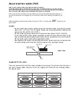
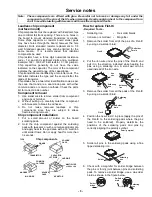
2. About lead free solder (PbF)
NOTE
Lead is listed as (Pb) in the periodic table of elements. / In the information below, Pb will refer to
lead solder, and PbF will refer to Lead Free Solder. / The lead free solder used in our
manufacturing process and discussed below is (Sn+Ag+Cu). / ThatisTin (Sn), Silver (Ag) and
Copper (Cu) although other types are available.
3
Summary of Contents for CT-32SC13-1G
Page 63: ... 50 A Board ...
Page 65: ... 52 ERJ6GEYJ183V NP2AH037AC ERENCES A Board ...
Page 66: ... 53 A Board ...
Page 69: ... 56 D Board ...
Page 70: ... 57 D Board ...
Page 71: ... 58 D Board ...
Page 74: ... 61 notes NOTES ...
Page 75: ... 62 G Board ...
Page 76: ... 63 G Board ...
Page 77: ... 64 G Board ...
Page 79: ... 66 L Board ...
Page 80: ... 67 L Board ...
Page 81: ... 68 A PCB ...
Page 82: ... 69 A PCB ...
Page 83: ... 70 D PCB ...
Page 84: ... 71 D PCB ...
Page 85: ... 72 G PCB ...
Page 86: ... 73 G PCB ...
Page 87: ... 74 L PCB ...
Page 88: ... 75 notes NOTES ...


