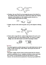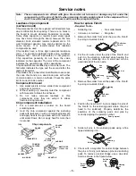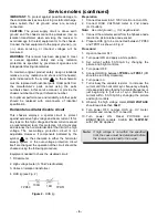
4. Position the new Flat IC in place (apply the pins of the Flat IC to
the soldering pads where the pins need to be soldered). Properly
determine the positions of the soldering pads and pins by
correctly aligning the polarity symbol
5. Solder all pins to the soldering pads using a fine tipped soldering
iron
6. Check with a magnifier for solder bridge between the pins or for
dry joint between pins and soldering pads. To remove a solder
bridge, use a de solder braid as shown in the figure below
IMPORTANT
To protect against possible damage to the solid state devices due to
arcing or static discharge, make certain that all ground wires are
securely connected
CAUTION
The power supply circuit is above earth ground and the chassis
cannot be polarized. Use an isolation transformer when servicing
the receiver to avoid damage to the test equipment or to the
chassis. Connect the test equipment to the proper ground(HOTor
7
Summary of Contents for CT-32SC13-1G
Page 63: ... 50 A Board ...
Page 65: ... 52 ERJ6GEYJ183V NP2AH037AC ERENCES A Board ...
Page 66: ... 53 A Board ...
Page 69: ... 56 D Board ...
Page 70: ... 57 D Board ...
Page 71: ... 58 D Board ...
Page 74: ... 61 notes NOTES ...
Page 75: ... 62 G Board ...
Page 76: ... 63 G Board ...
Page 77: ... 64 G Board ...
Page 79: ... 66 L Board ...
Page 80: ... 67 L Board ...
Page 81: ... 68 A PCB ...
Page 82: ... 69 A PCB ...
Page 83: ... 70 D PCB ...
Page 84: ... 71 D PCB ...
Page 85: ... 72 G PCB ...
Page 86: ... 73 G PCB ...
Page 87: ... 74 L PCB ...
Page 88: ... 75 notes NOTES ...


