


Precautions
•
Be sure to read the instructions for the vacuum pump,
vacuum pump adaptor and manifold gauge prior to use,
and follow the instructions carefully.
•
Make sure that the vacuum pump is filled with oil up to
the designated line on the oil gauge.
•
The gas pressure back flow prevention valve on the
charging hose is generally open during use. When you
are removing the charging hose from the service port, it
will come off more easily if you close this valve.
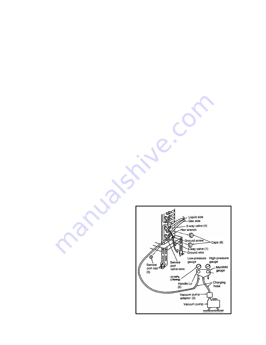
Fig. 12 Vacuum pump air purging configuration
b. Copper pipes
Use only copper pipes with the thickness given in table 10, and with minimal impurities. Because the surface of the pipe is
exposed, you should take special care, and also take measures such as marking the pipes to make sure they are easily
distinguished from other piping materials, to prevent mistaken use.
3. Precautions during refrigerant piping work
Take the following precautions on-site when connecting pipes. (Keep in mind that the need to control the entry of moisture and
dust is even more important that in conventional piping).
a. Keep the open ends of all pipes sealed until connection with AC equipment is complete.
b. Take special care when doing piping work on rainy days. The entering of moisture will degrade the refrigerating machine oil,
and lead to malfunctions in the equipment.
c.
Complete all pipe connections in as short a time as possible. If the pipe must be left standing for a long time after removing
the seal, it must be thoroughly purged with nitrogen, or dried with a vacuum pump.
11.4. Installation, transferring, servicing
11.4.1. Inspecting gas leaks with a vacuum pump for new installations (Using new
refrigerant piping)
1. From the viewpoint of protecting the global environment, please do not release refrigerant into the atmosphere.
a. Connect the projecting side (pin-pushing side) of the charging hose for the manifold gauge to the service port of the 3-way
valve. (1)
b. Fully open the handle Lo of the manifold gauge and run the vacuum pump. (2) (If the needle of the low-pressure gauge
instantly reaches vacuum, re-check step a).)
c.
Continue the vacuum process for at least 15 minutes, then check to make sure the low-pressure gauge has reached -0.1
MPa (-76 cmHg). Once the vacuum process has finished, fully close the handle Lo of the manifold gauge and stop the
vacuum pump operation, then remove the charging hose that is connected to the vacuum pump adaptor. (Leave the unit in
that condition for 1-2 minutes, and make sure that the needle of the manifold gauge does not return.) (2) and (3)
d. Turn the valve stem of the 2-way valve 90° counter-clockwise to open it, then, after 10 seconds, close it and inspect for a
gas leak (4)
e. Remove the charging hose from the 3-way valve service port, then open both the 2-way valve and 3-way valve. (1) (4) (Turn
the valve stem in the counter-clockwise direction until it gently makes contact. Do not turn it forcefully).
f.
Tighten the service port cap with a torque wrench (18 N.m (1.8 kgf.m)). (5) Then tighten the 2-way valve and 3-way valve
caps with a torque wrench (42 N.m (4.2 kgf.m)) or (55 N.m (5.5 kgf.m)). (6)
g. After attaching each of the caps, inspect for a gas leak around the cap area. (5) (6)
70
Summary of Contents for CS-F14DD3E5
Page 8: ...4 DIMENSIONS 4 1 CS F14DD3E5 CS F18DD3E5 8 ...
Page 9: ...4 2 CU B14DBE5 CU B18DBE5 9 ...
Page 10: ...5 REFRIGERATION CYCLE 5 1 CS F14DD3E5 CU B14DBE5 CS F18DD3E5 CU B18DBE5 10 ...
Page 11: ...6 BLOCK DIAGRAM 6 1 CS F14DD3E5 CS F18DD3E5 6 2 CU B14DBE5 11 ...
Page 12: ...6 3 CU B18DBE5 12 ...
Page 13: ...7 WIRING DIAGRAM 7 1 CS F14DD3E5 CS F18DD3E5 13 ...
Page 14: ...7 2 CU B14DBE5 14 ...
Page 15: ...7 3 CU B18DBE5 15 ...
Page 17: ...8 2 Remote control display 17 ...
Page 18: ...8 3 Remote control panel 18 ...
Page 85: ...13 TECHNICAL DATA 13 1 Sound data 85 ...
Page 86: ...86 ...
Page 87: ...13 2 Sound measurement point 13 2 1 Indoor unit 13 2 2 Outdoor unit 87 ...
Page 89: ...HEATING 89 ...
Page 91: ...91 ...
Page 93: ...93 ...
Page 95: ...13 5 Fan performance 13 5 1 CS F14DD3E5 Fan performance test report Fan performance curve 95 ...
Page 96: ...13 5 2 CS F18DD3E5 Fan performance test report Fan performance curve 96 ...
Page 99: ...14 REPLACEMENT PARTS 14 1 Indoor unit CS F14DD3E5 CS F18DD3E5 99 ...
Page 101: ...14 2 Outdoor unit CU B14DBE5 CU B18DBE5 101 ...
Page 102: ...CU B14DBE5 CU B18DBE5 102 ...
Page 104: ...15 PRINT PATTERN 15 1 Indoor unit INDOOR UNIT PRINTED CIRCUIT BOARD MAIN 104 ...


