


7
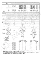
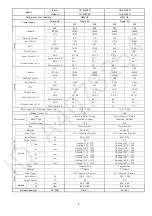
Indoor CS-A18PKD
CS-A24PKD
Model
Outdoor CU-A18PKD
CU-A24PKD
Performance Test Condition
NEW JIS
NEW JIS
Phase, Hz
Single, 50
Single, 50
Power Supply
V 220 230 220 230
kW 5.30 5.30 7.03 7.03
BTU/h 18100 18100 24000 24000
Capacity
kJ/h 19100 19100 25300 25300
Running Current
A
8.0
7.8
12.3
12.2
Input
Power
W 1.72k 1.76k 2.54k 2.58k
W/W 3.08 3.01 2.77 2.72
EER
BTU/hW 10.52 10.28 9.45
9.30
Power
Factor % 98 98 94 92
dB-A
43 / 38
43 / 38
47 / 41
47 / 41
Indoor Noise (H / L)
Power Level dB
59 / –
59 / –
63 / –
63 / –
dB-A
53 / –
54 / –
53 / –
54 / –
Cooling
Outdoor Noise (H / L)
Power Level dB
68 / –
69 / –
68 / –
69 / –
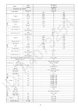
kW 5.65 5.70 7.80 7.80
BTU/h 19300 19400 26600 26600
Capacity
kcal/h 20300 20500 28100 28100
Running Current
A
7.7
7.6
12.2
12.2
Input
Power
W 1.65k 1.71k 2.53k 2.56k
W/W 3.42 3.33 3.08 3.05
COP
BTU/hW
11.70 11.35 10.51 10.39
Power
Factor % 97 98 94 91
dB-A
42 / 38
42 / 38
46 / 41
46 / 41
Indoor Noise (H / L)
Power Level dB
58 / –
58 / –
62 / –
62 / –
dB-A
54 / –
55 / –
54 / –
55 / –
Heating
Outdoor Noise (H / L)
Power Level dB
70 / –
71 / –
70 / –
71 / –
Max Current (A) / Max Input Power (W)
10.2 / 2.20k
14.6 / 3.25k
Starting Current (A)
40.0
60.0
Type
Hermetic Motor / Rotary
Hermetic Motor / Rotary
Motor Type
Induction (2-poles) Induction
(2-poles)
Compressor
Output Power
W
1.5k
2.0k
Type
Cross-flow Fan
Cross-flow Fan
Material
ASG30K1
ASG30K1
Motor Type
DC / Transistor (8-poles)
DC / Transistor (8-poles)
Input Power
W
94.8 - 94.8
94.8 - 94.8
Output Power
W
40
40
QLo rpm
Cooling: 910 - 910
Heating: 970 - 970
Cooling: 1010 - 1010
Heating: 1090 - 1090
Lo rpm
Cooling: 1000 - 1000
Heating: 1060 - 1060
Cooling: 1100 - 1100
Heating: 1180 - 1180
Me rpm
Cooling: 1110 - 1110
Heating: 1100 - 1100
Cooling: 1220 - 1220
Heating: 1220 - 1220
Hi rpm
Cooling: 1240 - 1240
Heating:1310 - 1310
Cooling: 1390 - 1390
Heating: 1530 - 1530
Indoor Fan
Speed
SHi
rpm
Cooling: 1310 - 1310
Cooling: 1530 - 1530
Type
Propeller Fan
Propeller Fan
Material
PP Resin
PP Resin
Motor Type
AC / Induction (6-poles)
AC / Induction (6-poles)
Input Power
W
138.3 - 150.3
138.3 - 150.3
Output Power
W
80
80
Lo
rpm
450 - 490
450 - 490
Outdoo
r Fa
n
Speed
Hi
rpm
815 - 830
815 - 830
Moisture Removal
L/h (Pt/h)
2.9 (6.1)
4.0 (8.5)
Summary of Contents for CS-A12PKD
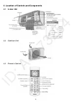
Page 12: ...12 4 Location of Controls and Components 4 1 Indoor Unit 4 2 Outdoor Unit 4 3 Remote Control...
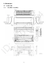
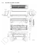
Page 13: ...13 5 Dimensions 5 1 Indoor Unit 5 1 1 CS A9PKD CS A12PKD...
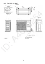
Page 14: ...14 5 1 2 CS A18PKD CS A24PKD CS A28PKD...
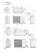
Page 15: ...15 5 2 Outdoor Unit 5 2 1 CU A9PKD 5 2 2 CU A12PKD...
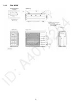
Page 16: ...16 5 2 3 CU A18PKD...
Page 17: ...17 5 2 4 CU A24PKD CU A28PKD...
Page 18: ...18 6 Refrigeration Cycle Diagram 6 1 CS A9PKD CU A9PKD CS A12PKD CU A12PKD...
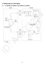
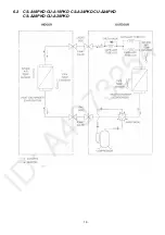
Page 19: ...19 6 2 CS A18PKD CU A18PKD CS A24PKD CU A24PKD CS A28PKD CU A28PKD...
Page 20: ...20 7 Block Diagram 7 1 CS A9PKD CU A9PKD...
Page 21: ...21 7 2 CS A12PKD CU A12PKD...
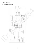
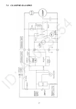
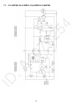
Page 22: ...22 7 3 CS A18PKD CU A18PKD CS A24PKD CU A24PKD...
Page 23: ...23 7 4 CS A28PKD CU A28PKD...
Page 28: ...28 9 Electronic Circuit Diagram 9 1 CS A9PKD CU A9PKD...
Page 29: ...29 9 2 CS A12PKD CU A12PKD...
Page 30: ...30 9 3 CS A18PKD CU A18PKD CS A24PKD CU A24PKD...
Page 31: ...31 9 4 CS A28PKD CU A28PKD...
Page 34: ...34 10 1 4 Comparator Printed Circuit Board 10 1 5 Human Activity Sensor Printed Circuit Board...
Page 40: ...40 11 2 5 Wire Stripping And Connecting Requirement...
Page 48: ...48 12 2 5 Wire Stripping And Connecting Requirement...
Page 87: ...87 Normal Deice Time Diagram Overload Deice Time Diagram...
Page 92: ...92 a Normal Deice Time Diagram b Overload Deice Time Diagram...
Page 98: ...98 Figure 3 Figure 4 17 1 1 3 To remove discharge grille Figure 5...
Page 100: ...100 Figure 9 Figure 10...
Page 104: ...104 Figure 20 Figure 21...
Page 105: ...105 18 Technical Data 18 1 Thermostat Characteristics...


