91
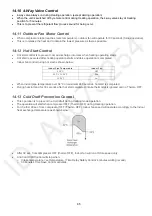
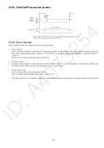
14.25 Cold Draft Prevention Control
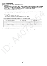
14.26 Deice Control
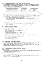
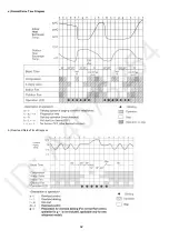
Deice starts to prevent frosting at outdoor heat exchanger.
•
Normal
Deice
Deice operation detection commences in Heating operation starts or 60 minutes after previous deice operation. If
the outdoor piping temperature drops to -4°C for 50 sec. continuously during compressor is in operation, deice
will start.
(There is no detection during Outdoor Fan stops.)
•
Overload
Deice
•
During heating operation, if the outdoor Fan OFF duration (due to overload protection control) is accumulated up
to 60 minutes and after compressor starts for 1 minute, deice starts.
•
Deice
ends
when
(a) 12 minutes after deicing operation starts;
(b) The outdoor piping temperature rises to about 12°C.
•
After deice operation, compressor stops for 30 seconds and 4-way valve stays at cooling position for 10 seconds.
Summary of Contents for CS-A12PKD
Page 12: ...12 4 Location of Controls and Components 4 1 Indoor Unit 4 2 Outdoor Unit 4 3 Remote Control...
Page 13: ...13 5 Dimensions 5 1 Indoor Unit 5 1 1 CS A9PKD CS A12PKD...
Page 14: ...14 5 1 2 CS A18PKD CS A24PKD CS A28PKD...
Page 15: ...15 5 2 Outdoor Unit 5 2 1 CU A9PKD 5 2 2 CU A12PKD...
Page 16: ...16 5 2 3 CU A18PKD...
Page 17: ...17 5 2 4 CU A24PKD CU A28PKD...
Page 18: ...18 6 Refrigeration Cycle Diagram 6 1 CS A9PKD CU A9PKD CS A12PKD CU A12PKD...
Page 19: ...19 6 2 CS A18PKD CU A18PKD CS A24PKD CU A24PKD CS A28PKD CU A28PKD...
Page 20: ...20 7 Block Diagram 7 1 CS A9PKD CU A9PKD...
Page 21: ...21 7 2 CS A12PKD CU A12PKD...
Page 22: ...22 7 3 CS A18PKD CU A18PKD CS A24PKD CU A24PKD...
Page 23: ...23 7 4 CS A28PKD CU A28PKD...
Page 28: ...28 9 Electronic Circuit Diagram 9 1 CS A9PKD CU A9PKD...
Page 29: ...29 9 2 CS A12PKD CU A12PKD...
Page 30: ...30 9 3 CS A18PKD CU A18PKD CS A24PKD CU A24PKD...
Page 31: ...31 9 4 CS A28PKD CU A28PKD...
Page 34: ...34 10 1 4 Comparator Printed Circuit Board 10 1 5 Human Activity Sensor Printed Circuit Board...
Page 40: ...40 11 2 5 Wire Stripping And Connecting Requirement...
Page 48: ...48 12 2 5 Wire Stripping And Connecting Requirement...
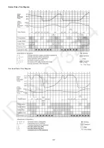
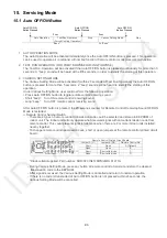
Page 87: ...87 Normal Deice Time Diagram Overload Deice Time Diagram...
Page 92: ...92 a Normal Deice Time Diagram b Overload Deice Time Diagram...
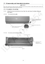
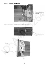
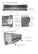
Page 98: ...98 Figure 3 Figure 4 17 1 1 3 To remove discharge grille Figure 5...
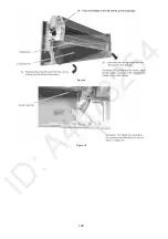
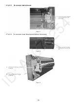
Page 100: ...100 Figure 9 Figure 10...
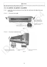
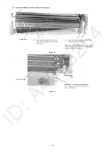
Page 104: ...104 Figure 20 Figure 21...
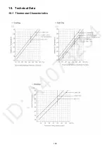
Page 105: ...105 18 Technical Data 18 1 Thermostat Characteristics...

