


56
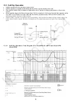
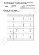
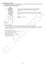
13.3 Soft Dry Operation
•
Soft Dry operation can be set using remote control.
•
Soft Dry operation is applied to dehumidify and to perform a gentle cooling to the room.
•
This operation starts when the intake air temperature sensor reaches the setting temperature on the remote
control.
•
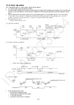
When operation begins, Soft Dry will be switched “ON” for a maximum 10 minutes, then Soft Dry operation will be
turn “OFF” for a minimum 6 minutes. After that, the Soft Dry operation will be “ON” and “OFF” based on the
setting temperature as shown in figure below.
•
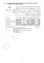
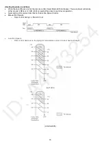
However after 3 minutes of compressor off, during Soft Dry “OFF” (within 6 minutes Soft Dry restart control), the
indoor unit will start to operate at normal Cooling mode if the intake temperature is higher than Cooling “ON”
point.
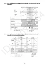
13.3.1 Soft Dry Operation Time Diagram (For CS-A9PK CU-A9PK and CS-A12PK
CU-A12PK)
Summary of Contents for CS-A12PKD
Page 12: ...12 4 Location of Controls and Components 4 1 Indoor Unit 4 2 Outdoor Unit 4 3 Remote Control...
Page 13: ...13 5 Dimensions 5 1 Indoor Unit 5 1 1 CS A9PKD CS A12PKD...
Page 14: ...14 5 1 2 CS A18PKD CS A24PKD CS A28PKD...
Page 15: ...15 5 2 Outdoor Unit 5 2 1 CU A9PKD 5 2 2 CU A12PKD...
Page 16: ...16 5 2 3 CU A18PKD...
Page 17: ...17 5 2 4 CU A24PKD CU A28PKD...
Page 18: ...18 6 Refrigeration Cycle Diagram 6 1 CS A9PKD CU A9PKD CS A12PKD CU A12PKD...
Page 19: ...19 6 2 CS A18PKD CU A18PKD CS A24PKD CU A24PKD CS A28PKD CU A28PKD...
Page 20: ...20 7 Block Diagram 7 1 CS A9PKD CU A9PKD...
Page 21: ...21 7 2 CS A12PKD CU A12PKD...
Page 22: ...22 7 3 CS A18PKD CU A18PKD CS A24PKD CU A24PKD...
Page 23: ...23 7 4 CS A28PKD CU A28PKD...
Page 28: ...28 9 Electronic Circuit Diagram 9 1 CS A9PKD CU A9PKD...
Page 29: ...29 9 2 CS A12PKD CU A12PKD...
Page 30: ...30 9 3 CS A18PKD CU A18PKD CS A24PKD CU A24PKD...
Page 31: ...31 9 4 CS A28PKD CU A28PKD...
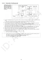
Page 34: ...34 10 1 4 Comparator Printed Circuit Board 10 1 5 Human Activity Sensor Printed Circuit Board...
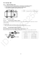
Page 40: ...40 11 2 5 Wire Stripping And Connecting Requirement...
Page 48: ...48 12 2 5 Wire Stripping And Connecting Requirement...
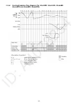
Page 87: ...87 Normal Deice Time Diagram Overload Deice Time Diagram...
Page 92: ...92 a Normal Deice Time Diagram b Overload Deice Time Diagram...
Page 98: ...98 Figure 3 Figure 4 17 1 1 3 To remove discharge grille Figure 5...
Page 100: ...100 Figure 9 Figure 10...
Page 104: ...104 Figure 20 Figure 21...
Page 105: ...105 18 Technical Data 18 1 Thermostat Characteristics...


