69
13.10 Quiet Operation
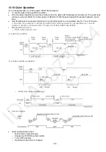
(For Cooling Operation or cooling region of Soft Dry Operation)
•
To provide quiet cooling operation condition.
•
Once the Quiet Operation is set at the remote control, the Quiet LED brightness will be dimmed. The sound level
will reduce around 2dB(A) for Lo fan speed or 3dB(A) for Hi/Me fan speed against the present operation sound
level.
•
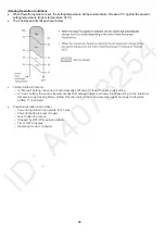
Dew formation become severe at Quite Lo Cool, therefore Quiet Lo cool operated only for 1 hour 30 minutes
(1 hour QLo, 30 minutes QLo + 80rpm) (for A9PK and A12PK) and Quiet Lo cool operated only 1 hour 30
minutes (1 hour QLo, 30 minutes QLo + 50 rpm) (for A18PK, A24PK and A28PK).
•
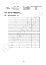
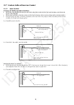
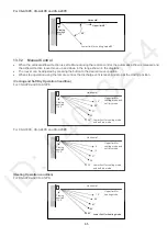
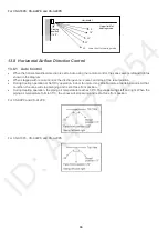
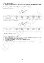
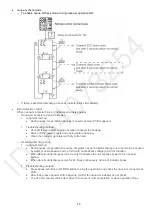
Manual Airflow Direction:
o
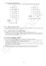
RPM control during Lo cool
(For A9PK and A12PK)
(For A18PK, A24PK and A28PK)
o
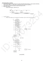
RPM control during Hi & Me cool
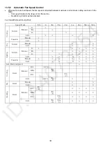
•
Auto Fan Speed
•
Quiet operation stops when:
o
Quiet button is pressed again.
o
Stopped by OFF/ON operation button.
o
Timer OFF activates.
o
Operation mode button is changed.
Summary of Contents for CS-A12PKD
Page 12: ...12 4 Location of Controls and Components 4 1 Indoor Unit 4 2 Outdoor Unit 4 3 Remote Control...
Page 13: ...13 5 Dimensions 5 1 Indoor Unit 5 1 1 CS A9PKD CS A12PKD...
Page 14: ...14 5 1 2 CS A18PKD CS A24PKD CS A28PKD...
Page 15: ...15 5 2 Outdoor Unit 5 2 1 CU A9PKD 5 2 2 CU A12PKD...
Page 16: ...16 5 2 3 CU A18PKD...
Page 17: ...17 5 2 4 CU A24PKD CU A28PKD...
Page 18: ...18 6 Refrigeration Cycle Diagram 6 1 CS A9PKD CU A9PKD CS A12PKD CU A12PKD...
Page 19: ...19 6 2 CS A18PKD CU A18PKD CS A24PKD CU A24PKD CS A28PKD CU A28PKD...
Page 20: ...20 7 Block Diagram 7 1 CS A9PKD CU A9PKD...
Page 21: ...21 7 2 CS A12PKD CU A12PKD...
Page 22: ...22 7 3 CS A18PKD CU A18PKD CS A24PKD CU A24PKD...
Page 23: ...23 7 4 CS A28PKD CU A28PKD...
Page 28: ...28 9 Electronic Circuit Diagram 9 1 CS A9PKD CU A9PKD...
Page 29: ...29 9 2 CS A12PKD CU A12PKD...
Page 30: ...30 9 3 CS A18PKD CU A18PKD CS A24PKD CU A24PKD...
Page 31: ...31 9 4 CS A28PKD CU A28PKD...
Page 34: ...34 10 1 4 Comparator Printed Circuit Board 10 1 5 Human Activity Sensor Printed Circuit Board...
Page 40: ...40 11 2 5 Wire Stripping And Connecting Requirement...
Page 48: ...48 12 2 5 Wire Stripping And Connecting Requirement...
Page 87: ...87 Normal Deice Time Diagram Overload Deice Time Diagram...
Page 92: ...92 a Normal Deice Time Diagram b Overload Deice Time Diagram...
Page 98: ...98 Figure 3 Figure 4 17 1 1 3 To remove discharge grille Figure 5...
Page 100: ...100 Figure 9 Figure 10...
Page 104: ...104 Figure 20 Figure 21...
Page 105: ...105 18 Technical Data 18 1 Thermostat Characteristics...

