background image

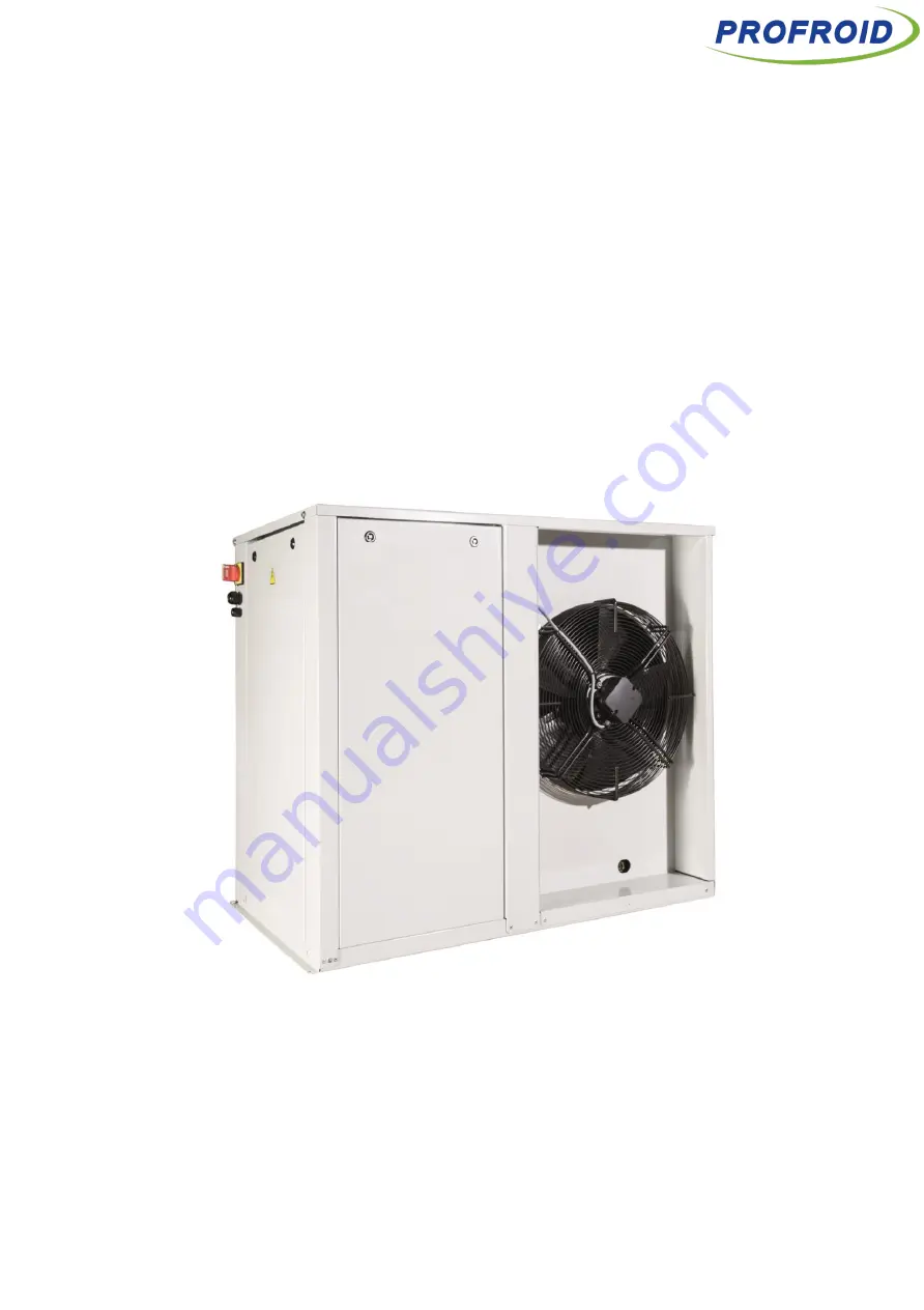
OPERATING INSTRUCTIONS  


COMMISSIONING / OPERATING / MAINTENANCE 


(must be given to the end user in order to complete the operating manual during the equipment service life) 


QUIETCO

2

OL 


/ PED fluid group : 2 


These operating instructions must be read at the delivery of the equipment and prior any operation on it. 

Our technical department is at your disposal for any additional information (Tel : + 33 4 42 18 05 00). 

This document is a translation of the French original version which prevails in all cases. 


Version 9110 


Summary of Contents for QC LT

Page 1: ...ent service life QUIETCO2OL PED fluid group 2 These operating instructions must be read at the delivery of the equipment and prior any operation on it Our technical department is at your disposal for any additional information Tel 33 4 42 18 05 00 This document is a translation of the French original version which prevails in all cases Version 9110 ...

Page 2: ... remarks on transportation P 14 Warning concerning the mounting of the liquid lines P 16 Commissioning Instruction on water cooled units P 18 19 20 Recommendation on the evaporator controller selection P 24 Clarification of the Controller settings P 26 Clarification for the gascooler cleaning instructions P 32 Update on the service instruction P 33 34 Clarification of the meaning of the colour cod...

Page 3: ...ON LOCATION 13 14 REFRIGERANT PIPING WORK 15 16 COMMISSIONING 17 19 OPERATING 20 REFRIGERANT CIRCUIT DIAGRAM 21 22 ELECTRICAL CONNECTIONS 23 24 USER INTERFACE 25 27 DESCRIPTION OF THE DISPLAY 28 29 MANUAL MODE FOR THE VACUUM PROCEDURE 30 CONTROL FUNCTIONS 31 MAINTENANCE 32 34 WARRANTY CONDITIONS 35 36 ECODESIGN 37 APPENDIX 1 REFRIGERANT AND OIL CHARGE 38 42 APPENDIX 2 ALARM LIST 43 44 ...

Page 4: ...t and handling of pressure devices Install device in a space with sufficient ventilation regarding standards and regulations because device is under pressure of nitrogen except dry cooler brine air cooler Very important before performing any servicing operation on refrigeration equipment the electric power supply must be turned off The contractor or the company in charge of the installation shall ...

Page 5: ...age of refrigerant Make sure that flexible hoses are not in contact with metalparts The products added for thermal and or acoustic insulation must be neutral with respect to support materials The protection devices pipings and accessories must be protected against unfavourable effects from the environment Make sure that access and emergency exit ways are not obstructed to comply with the local reg...

Page 6: ...the possible increase of pressure in the part of device which is isolated The periodic technical checks must be made following frequencies determined by standards sound engineering practice end user and installer Report periodic checks and analyze the data In case of abnormalities or inconsistencies determine the cause and correct it In case of hanged units evaporator as an example it is necessary...

Page 7: ...hould not be judged by the speed at which the level of vacuum is reached but on the effective time it is held 24 hours at 0 7 mbar is a good standard The total increase in pressure after that period should not be more than 2 6 mbar The residual moisture in the system should be less than 10 ppm When the installation is under vacuum an insulation check of the motor should not be carried out The comp...

Page 8: ...a low level the cold cylinder should be disconnected and allowed to warm After the cylinder has been warmed up the residual R744 can be removed In the meantime another warm tank can be connected to the system to continue the chargingprocess Do not charge liquid on compressor suction line Only Gas Charge the machine only in vapour phase The charge should be done on the suction line Never charge the...

Page 9: ...tives the safety rules generally recognized sound engineering practice the local regulations as well as those which may be set up taking into account the evolution of the technology and the regulations If the installation the commissioning the operating the maintenance are not realised according to this operating instructions the responsibility of Profroid cannot be involved Completely inform the ...

Page 10: ...icalshock Do not change the set values of the safety device Using the refrigeration unit with changed values may cause failure of the safety stop function and lead to a burst or fire When abnormal operation is detected or before starting disassembly or repair turn off the main powerswitch Specified components must be used for repair Use of non specified components may cause failure of the safety s...

Page 11: ...partment Filter drier Service valve liquid line Sight glass Compressor HP safety pressure switch EC1 HP Control valve EC3 Control valve intermediate pressure Gas cooler HP service valve Service valve Suction line LP HP Pressure transducer Shut off valves liquid line ...

Page 12: ...re transducer Service valve liquid line EC3 Control valve intermediate pressure Regulating thermostatic valve Plate Heat Exchanger intercooler 3 ways valve Plate Heat Exchanger By pass valve gas cooler Sight glass Filter drier Service valve liquid line Service valve suction line LT compressor Parallel compressor EC1 HP Control valve Oil separator HP service valve Solenoid valve Pressostat de sécur...

Page 13: ...mbient Temperature 15 C 43 C the ambient temperature can be 30 C if polar kit heater is installed Relative Humidity 10 90 Allowed fluids Water Water glycol MPG MEG 60 maxi Water circuit water cooled version Water inlet temperature 8 C to 35 C nominal 7 C 12 C Water mass flow Variable depend on the capacity Pressure drop water side 50 kPa or below On off cycle period 5 min or longer for on off cycl...

Page 14: ...CO2OL serie Water cooled QC MT30 QC MT50 QC MT67 QC MT100 QC LT75 QC LT167 QC MT QC LT Fig 1 Fig 3 Fig 2 Fig 4 Fig 5 Fig 6 Dimensions Length mm 1200 1200 1200 1200 1200 1200 1200 1200 Depth mm 360 390 390 390 690 811 390 690 Height mm 1028 1028 1028 1430 1028 1638 1028 1028 Weight kg 125 130 160 185 185 210 175 250 ...

Page 15: ... qualified professional should be certified and will wear individual safety equipment protective gloves glasses safety shoes etc operators will never circulate under the load during lifting operations FORKLIFT When carrying the refrigeration unit by a forklift use a packaging wood base or pallet for maintaining the refrigeration unit in the vertical position CRANE When carrying the refrigeration u...

Page 16: ...necessary rules Enough free space all around the refrigeration equipment should be provided to facilitate maintenance operations The heat exchangers must be installed in locations free of any external dust or other pollutants from the neighborhood which could obstruct or clog the coils If devices are used in a corrosive area sea side pollutant gas etc make sure that appropriate anticorrosion prote...

Page 17: ...other one In the case of face to face installation keep a minimum of 2000mm distance between the units Important For transportation purpose the cable glands have been placed in reverse position Please place them in the right position before installing the unit 2000 mm Normal mounting Mounting for transportation ...

Page 18: ...ping s are connected to the appropriate pressurized equipment EN378 2 Product Suction line R744 Liquid line R744 PS MT30 9 52 mm 3 8 9 52 mm 3 8 80 bars MT50 9 52 mm 3 8 9 52 mm 3 8 80 bars MT67 9 52 mm 3 8 9 52 mm 3 8 80 bars MT100 9 52 mm 3 8 9 52 mm 3 8 80 bars LT75 9 52 mm 3 8 9 52 mm 3 8 80 bars LT167 12 7 mm 1 2 9 52 mm 3 8 80 bars Prevent contamination of foreign objects such as dust metal ...

Page 19: ...nst unfavorable effects from the environment The liquid line piping should be considered as an extension of the condensing unit receiver A special attention must be paid to the piping path and the thermal insulation In case of exposure to heat source piping path exposed to the sun and not protected piping path through non ventilated attic The liquid inside the piping can be vaporized and can cause...

Page 20: ...olerance of 10 with respect to the rated value Specific protection is provided according to the neutral system Any on site wiring must comply with the legal standards in force in the country of installation including grounding Before turning on a device make surethat the electric connections have been correctly made the clamping screws of the various terminals are correctly tightened Check the pos...

Page 21: ...rsion WCO are set from the factory In case of replacement follow the procedure below 1 Complete set Disassembly of the engine Unscrew the engine with the dedicated tool control handle 2 Check the valve position as indicated 3 Disengage the engine if necessary ...

Page 22: ...SSIONING 19 Thermostatic valve water cooled version After replacing it make sure to set the thermostatic valve according to the factory settings Graduation 2 5T which correspond to a temperature of 45 C CO2 ...

Page 23: ...ctive and recommendations of these operating instructions Results of design calculations checks and test reports in relation with low voltage directive are archived Water cooled QUIETCO2OL features The cooling fluid of the Water Cooled QUIETCO2OL must either be water or a mixture of water and MEG or water and MPG maximum MEG MPG concentration 60 The inlet temperature of this fluid must be in a 8 C...

Page 24: ...REFRIGERANT CIRCUIT DIAGRAM 21 QUIETCO2OL AIR COOLED MT Version LT Version ...

Page 25: ...REFRIGERANT CIRCUIT DIAGRAM 22 QUIETCO2OL WATER COOLED VERSION MT Version LT Version ...

Page 26: ...T QC 67MT QC 100MT QC 75LT QC 167LT Power supply 230 V Single phase 50 Hz G 400 V 3ph 50 Hz N G 230 V Single phase 50 Hz G 400 V 3 ph 50 Hz N G Max absorbed current without evaporators Air cooled 13 3 A 20 7 A 27 2 A 18 5 A 18 4 A 31 4 A Max absorbed current without evaporators Water cooled 12 5 A 19 9 A 26 4 A 16 5 A 17 6 A 31 4 A If consumers are powered from the condensing unit using the availa...

Page 27: ...nds of controller or expansion valve a special attention must be paid on the settings on site Bad settings of these components can lead to an instability of the system short cycling the compressor and oil return issue endangering the condensing unit operation To avoid any overloading of the compressors it is necessary to set a MOP Maximum Operating Pressure of 0 C 34 8 Bar for MT application and a...

Page 28: ...oard pRack Hecu automatically returns to the main mask 5 min after the last button was pressed An example of the main mask is shown in the figure highlighting the fields and icons used 1 Time and date 2 Main values 3 Unit status unit off compressors and fan status uniton 4 Active alarm signal and manual operation 5 Access further information mask menu branch A a by pressing Note the information sh...

Page 29: ... receiver is below 55 Bar on MT unit Label Description Unit Min Max Setpoint MT LT Cab03 Compressor pressure barg 10 0 40 0 26 5 13 0 Cae24 Suction high pressure alarm threshold absolute barg 60 0 Cae26 Suction low pressure alarm threshold absolute barg 10 0 5 5 Caf17 Minimum on time compressor s 0 999 120 Caf17 Minimum off time compressor s 0 999 180 Caf17 Minimum time to start same compressor s ...

Page 30: ...USER INTERFACE 27 Navigation To navigate inside the menu tree use the following buttons ...

Page 31: ...rity of the compressors f Configuration Hardware configuration of the system g Advanced Advanced configuration of the system D Condensers a I O status Configuration and status of the gascooler s inputs outputs b Regulation Parameters of the gascooler s regulation c Driver EVD Not used d Energy saving Energy saving HP floating winter time difference e Alarms Configuration of the LP HP security of t...

Page 32: ...es and liquid receivers definition G Settings a Clock a Scheduler Hourly weekly scheduling b Adjustment Internal clock setup date and time b Langage Language setting of the regulator English only at the moment c BMS Adress and communication speed setup d Fieldbus Communication port setup of the Fieldbus e Passwords Access passwords and access level modification password modification is discouraged...

Page 33: ...e L1 Suction Press enter to enable L1 Discharge Use arrows and enter to set the timeout 15 min Once the specified time has been reached both L1 Suction and L1 Discharge manual management will be disabled Once the evacuation procedure is done either wait for the timeout to end or go back to this menu to disable manual management Press enter to continue Manual management of HPV EC1 valve Use this fu...

Page 34: ...t 5 times before alarm becomes manual Compressor out of envelope alarm Compressor auto reset 5 times before alarm becomes manual EC Gas cooler fan is protected by internal temperaturesensor Automatic reset All alarms are visible after pressing the flashing red warning triangle Hold down to reset Example here suction pressure probe broken or disconnected Alarm list A complete list of controller ala...

Page 35: ...for at least two hours each week Every month carry out an operating check on Cleanliness of coil Refrigerant level Minimum every year Clean the gas cooler Instructions or recommendations appearing in the various technical advice notes and manufacturer s service manuals should be followed precisely Please contact our Technical Department for any additional information Cleaning Coils should preferab...

Page 36: ......

Page 37: ... frozen water present in the distributor Clean or defrost evaporator 5 Suction pressure too high MOP Set a MOP on the evaporator controller see P 24 Restart after defrost Wait for confirmation Compression problem Change compressor 6 Gas cooler pressure too high Insufficient flow of air into the gas cooler Clean the gas cooler Check motor fans Installation overcharged Drain liquid into reservoir Ai...

Page 38: ...compressor motor does not start Low pressure switch cuts out See paragraph 3 High pressure switch cuts out See paragraph 6 Fuses burn out Check the cause and change fuses Anti short cycle time delay relay is in operation Wait Internal security switched out Check cause of increase in motor winding temperatures Main circuit breaker open Close circuit breaker 13 Compressor works continuously Control ...

Page 39: ...aminants debris metal powder etc entering in the cycle during the installation or pipingwork When the failure is judged as incorrect wiring work during installation and piping work When the personnel related to our company pointed out incorrect work but no improvement was made Incident caused by violating laws andregulations When the system was operated by knowing large vibration or operation soun...

Page 40: ...l component caused by abnormally high voltage applied to the source such as lightening or excessive noise such as arc spark etc Incident caused by unspecified voltage condition or Incident caused by applying distorted voltage of a general purposeinverter Incident caused by using a ground fault interrupter not specified by our company Incident caused by not conforming to the range of evaporating te...

Page 41: ...lidity SEPR VALIDITY Annual electric consum Rated COP Seasonal energy perfom ratio kW kWh a MT30PK 2 71 6 974 1 76 YES MT50PK 4 10 10 608 1 76 YES MT67PK 6 04 15 016 2 47 YES MT100PK 8 20 20 431 2 47 YES LT75PK 2 94 11 599 1 89 YES LT167PK 6 54 26 798 1 82 YES NB Water cooled versions are not concerned by Ecodesign ...

Page 42: ...e at the bottom and additional oil charge at the top In this particular example the R744 charge equals 7 8 kg and an additional oil charge of 60 mL is required Remark Given the uncertainties on site concerning the real volume of the equipment we recommend using the complete volume of any opened oil container delivered in addition with the unit The installer also has to consider the zone of this cr...

Page 43: ...APPENDIX 1 REFRIGERANT AND OIL CHARGE AIR COOLED VERSION 39 ...

Page 44: ...APPENDIX 1 REFRIGERANT AND OIL CHARGE AIR COOLED VERSION 40 ...

Page 45: ...ND OIL CHARGE WATER COOLED VERSION 41 Evaporator volume based on filling factor of 20 Oil charge in kg Pipe length CO2 Charge in kg CO2 Charge in kg Evaporator volume based on filling factor of 20 Oil charge in kg Pipe length ...

Page 46: ...HARGE WATER COOLED VERSION 42 Evaporator volume based on filling factor of 20 Oil charge in kg Evaporator volume based on filling factor of 20 Oil charge in kg CO2 Charge in kg Pipe length Pipe length Charge CO2 en kg CO2 Charge in kg ...

Page 47: ...onfig ALB16 Low suction pressure alarm Automatic Config ALC01 Alarm 1 compressor 1 Man Autom Config Shutdown compressor ALC02 Alarm 2 compressor 1 Man Autom Config Shutdown compressor ALC05 Alarm comp backup Man Autom Config Shutdown compressor ALG01 Clock board error Automatic Related functions disabled ALG02 Extended memory error Automatic Related functions disabled ALG11 High thermostat alarms ...

Page 48: ...re number Low temperature alarm Generic probe 2 Display only refer to 0300055IT MPXPRO manual ALW44 57 70 83 96 Store number High temperature alarm Generic Probe 2 Display only refer to 0300055IT MPXPRO manual ALW45 58 71 84 97 Store number Defrost timeout Display only refer to 0300055IT MPXPRO manual ALW46 59 72 85 98 Store number Low superheat alarm Display only refer to 0300055IT MPXPRO manual ...

Page 49: ...PROFROID CARRIER S C S 178 rue du Fauge ZI Les Paluds B P 1152 13782 Aubagne Cedex France International Tel 33 4 42 18 05 00 Fax 33 4 42 18 05 02 ...

Reviews: