


41
11.2 Indoor Unit
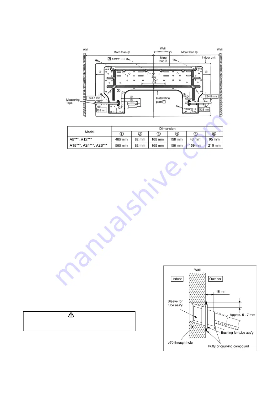
11.2.1
How to Fix Installation Plate
The mounting wall is strong and solid enough to prevent if from the vibration.
The centre of installation plate should be at more than
c
at right and left of the wall.
The distance from installation plate edge to ceiling should more than
d
.
From installation plate left edge to unit’s left side is
e
.
From installation plate right edge to unit’s right side is
f
.
ƻ
B
: For left side piping, piping connection for liquid should be about
g
from this line.
: For left side piping, piping connection for gas should be about
h
from this line.
1
Mount the installation plate on the wall with 5 screws or more (at least 5 screws).
(If mounting the unit on the concrete wall, consider using anchor bolts.)
o
Always mount the installation plate horizontally by aligning the marking-off line with the thread and using
a level gauge.
2
Drill the piping plate hole with ø70mm hole-core drill.
o
Putting measuring tape at position as shown in the diagram above.
The hole centre is obtained by measuring the distance namely 128 mm for left and right hole
respectively. Another method is intersection point of arrow mark extension.
The meeting point of the extension arrow mark is the hole center position.
o
Drill the piping hole at either the right or the left and the hole should be slightly slanting to the outdoor
side. (refer to step 3)
11.2.2
To Drill a Hole in the Wall and
Install a Sleeve of Piping
1
Insert the piping sleeve to the hole.
2
Fix the busing to the sleeve.
3
Cut the sleeve until it extrudes about 15mm
from the wall.
Caution
When the wall is hollow, please be sure to use the sleeve for tube
ass’y to prevent dangers caused by mice biting the connecting
cable.
4
Finish by sealing the sleeve with putty or
caulking compound at the final stage.
Summary of Contents for CS-A12KKD-2
Page 3: ...3 18 Exploded View and Replacement Parts List 125 18 1 Indoor Unit 125 18 2 Outdoor Unit 131 ...
Page 16: ...16 4 Location of Controls and Components 4 1 Indoor Unit 4 2 Outdoor Unit 4 3 Remote Control ...
Page 17: ...17 5 Dimensions 5 1 Indoor Unit 5 1 1 CS A9KKD 2 CS A12KKD 2 ...
Page 18: ...18 5 1 2 CS A18KKD 2 CS A24KKD 2 CS A28KKD 2 ...
Page 19: ...19 5 2 Outdoor Unit 5 2 1 CU A9KKD 2 5 2 2 CU A12KKD 2 ...
Page 20: ...20 5 2 3 CU A18KKD 2 CU A24KKD 2 CU A28KKD 2 ...
Page 21: ...21 6 Refrigeration Cycle Diagram 6 1 CS A9KKD 2 CU A9KKD 2 CS A12KKD 2 CU A12KKD 2 ...
Page 22: ...22 6 2 CS A18KKD 2 CU A18KKD 2 CS A24KKD 2 CU A24KKD 2 CS A28KKD 2 CU A28KKD 2 ...
Page 23: ...23 7 Block Diagram 7 1 CS A9KKD 2 CU A9KKD 2 ...
Page 24: ...24 7 2 CS A12KKD 2 CU A12KKD 2 ...
Page 25: ...25 7 3 CS A18KKD 2 CU A18KKD 2 CS A24KKD 2 CU A24KKD 2 ...
Page 26: ...26 7 4 CS A28KKD 2 CU A28KKD 2 ...
Page 31: ...31 9 Electronic Circuit Diagram 9 1 CS A9KKD 2 CU A9KKD 2 ...
Page 32: ...32 9 2 CS A12KKD 2 CU A12KKD 2 ...
Page 33: ...33 9 3 CS A18KKD 2 CU A18KKD 2 CS A24KKD 2 CU A24KKD 2 ...
Page 34: ...34 9 4 CS A28KKD 2 CU A28KKD 2 ...
Page 36: ...36 10 1 1 2 CS A28KKD 2 ...
Page 39: ...39 10 1 7 Eco Patrol Printed Circuit Board ...
Page 86: ...86 Normal Deice Time Diagram Overload Deice Time Diagram ...
Page 91: ...91 a Normal Deice Time Diagram b Overload Deice Time Diagram ...
Page 97: ...97 Figure 3 Figure 4 Figure 5 16 1 1 3 To remove discharge grille Figure 6 ...
Page 99: ...99 Figure 10 Figure 11 ...
Page 101: ...101 16 2 1 3 To remove power electronic controller Figure 14 Figure 15 Figure 16 Figure 17 ...
Page 103: ...103 Figure 21 Figure 22 Figure 23 ...
Page 104: ...104 17 Technical Data 17 1 Thermostat Characteristics ...


