


176
Parameter Function
Protocol
Please select protocol from the dropdown list.
Address
Set corresponding dome address. Default value is 1.
Please note your
setup here shall comply with your dome address; otherwise you
cannot control the speed dome.
Baud Rate Select the dome baud rate. Default setup is 9600.
Data Bit
Default setup is 8. Please set according to the speed dome dial switch
setup.
Stop bit
Default setup is 1. Please set according to the speed dome dial switch
setup.
Parity
Default setup is none. Please set according to the speed dome dial
switch setup.
5.8.5.5 ATM/POS
The ATM/POS function is for financial areas. It includes Sniffer, information analysis and
title overlay function. The Sniffer mode includes COM and network.
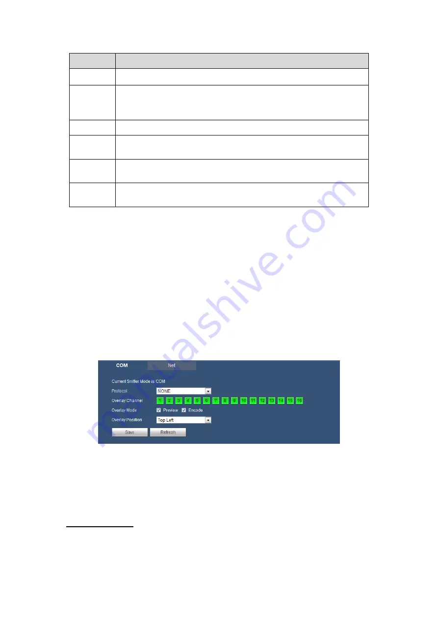
5.8.5.5.1 COM Type
The COM interface is shown as below. See Figure
Protocol: Please select from the dropdown list according to your actual situation.
Overlay channel: Please select the channel you want to overlay the card number.
Overlay mode: There are two options: preview and encode. Preview means overlay
the card number in the local monitor video. Encode means overlay the card number
in the record file.
Overlay Position: Here you can select the proper overlay position from the dropdown
list.
Figure
5-75
5.8.5.5.2 Network Type
The network type interface is shown as below. See Figure
Here we take the ATM/POS protocol to continue.
There are two types: with or without the protocol according to client
’s requirements.
With the protocol
For ATM/POS with the protocol, you just need to set the source IP, destination IP
(sometimes you need to input corresponding port number).
Summary of Contents for CJ-HDR216
Page 1: ...HD Analog Recorder User s Manual Model No CJ HDR216 CJ HDR416 Version 1 0 3 ...
Page 93: ...85 Figure 4 72 Figure 4 73 ...
Page 94: ...86 Figure 4 74 Figure 4 75 ...
Page 99: ...91 Figure 4 79 Figure 4 80 ...
Page 102: ...94 Figure 4 84 Figure 4 85 ...
Page 108: ...100 Figure 4 93 Figure 4 94 ...
Page 110: ...102 Figure 4 96 Figure 4 97 ...
Page 116: ...108 Figure 4 104 Figure 4 105 ...
Page 120: ...112 Figure 4 109 Figure 4 110 ...
Page 130: ...122 Figure 4 120 Figure 4 121 ...
Page 164: ...156 Figure 5 46 Figure 5 47 ...
Page 168: ...160 Figure 5 51 Figure 5 52 Please refer to the following sheet for detailed information ...
Page 172: ...164 Blue color stands for MD alarm record snapshot Figure 5 56 Figure 5 57 ...


