background image

Operating Instructions

„

„

PoE++ 

*

4

 eliminates need for camera power 

configurations

• Configurations for camera's power supply are not necessary when 

the unit is connected to a network device that supports the PoE++ 

standard (IEEE 802.3bt compliant)

*

5

 .


Software authentication (LLDP) is also supported, but it may be 

necessary to make settings on the network device (IEEE 802.3bt 

compliant)

*

5

.

<NOTE>

• If the AC adaptor and a PoE++ power supply are connected 

simultaneously, the AC adaptor will have priority. If the AC adaptor 

is disconnected while both power supplies are connected, the unit 

will restart automatically, and the image will be interrupted.

• Use a Category 5e cable or higher when using a PoE++ power 

supply. The maximum length of the cable between the power 

supply unit and the unit is 100 meters (328 ft). Using a cable that 

is lower than Category 5e may result in reduced power supply 

capabilities.

*

4


Power over Ethernet Plus Plus. Referred to as "PoE++" in this 

manual.

*

5


For details on PoE++ power supply devices for which operation 

has been verified, consult your local dealer.

Accessories

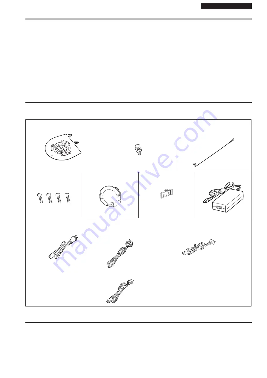
Check that the following accessories are present and accounted for.

• After removing the product from its container, dispose of the power cable cap (if supplied) and packing materials in an appropriate manner.

 Mount bracket for installation surface 

(Hanging/Desktop) (1)

Main unit mounting screw (with flat 

washer, spring washer) 

M3×6 mm (1/4 inches) (1)

Drop‑prevention wire (1)

Drop‑prevention wire mounting screw (1) 

(comes attached to the unit)

 Bracket mounting screws 

(bind‑head) 

M4×10 mm (13/32 inches) (4)

Lens cap (1)

(comes attached to the unit)

Pan stopper (1)

(comes attached to the unit)

AC adaptor (1)

 Power cable

for  AW‑UE80WP, AW‑UE80KP (1)

for AW‑UE80WE, AW‑UE80KE (2)

for AW‑UE80WED, AW‑UE80KED (1)


For U.K. and Saudi Arabia


For Continental Europe, etc.


For India only


Optional accessories

„

z

Wireless remote control AW‑RM50AG (Size “AA” dry battery x 2, obtained separately)

„

z

Direct ceiling mount bracket WV‑Q105A

<NOTE>

• For details on optional accessories, refer to the catalog or consult your local dealer.

42

43

Features (continued)

Summary of Contents for AW-UE80KP

Page 1: ...ploi et les instructions d installation ESPAÑOL Antes de instalar y usar este producto asegúrese de leer Lea esto primero páginas 4 33 a 35 Si desea obtener más información visite el sitio web de Panasonic https pro av panasonic net manual en index html y consulte las instrucciones de funcionamiento y las instrucciones de instalación DEUTSCH Bitte lesen Sie sorgfältig Bitte lesen Sie zuerst diesen...

Page 2: ...rnet Explorer 11 only are indicated using the mark The screenshots are used in accordance with the guidelines of Microsoft Corporation български Посетете следния уебсайт относно информация за безопасността и важни уведомления за продукта Hrvatski Za sigurnosne informacije i važne obavijesti o proizvodu posjetite sljedeću internetsku stranicu Čeština Na následujícím webu najdete bezpečnostní inform...

Page 3: ...KE AW UE80WED AW UE80KED 27 Read this first For AW UE80WE AW UE80KE 28 Lire ces informations en premier AW UE80WP AW UE80KP 30 Lire ces informations en premier AW UE80WE AW UE80KE 31 Lea esto rimero Para AW UE80WP AW UE80KP 33 Lea esto primero Para AW UE80WE AW UE80KE 34 Bitte lesen Sie zuerst diesen Hinweis Für AW UE80WE AW UE80KE 36 Leggere prima quanto segue Per AW UE80WE AW UE80KE 38 Read this...

Page 4: ...méra est conçue pour être utilisée uniquement avec la potence de fixation fournie avec l appareil ou avec la potence de fixation directe au plafond Panasonic WV Q105A L utilisation de tout autre dispositif risque de se traduire par une instabilité et être cause de blessures à des personnes ATTENTION Pour réduire les risques d incendie ou d électrocution faire l installation en s assurant que les v...

Page 5: ... nicht mit in der Wand verlegten elektrischen Leitungen in Berührung kommen ist die Sicherheitsinformation Leggere prima quanto segue AVVISO Per prevenire ferite questo apparecchio deve essere montato saldamente al pavimento muro in conformità alle istruzioni di installazione AVVISO L installazione deve essere realizzata unicamente da tecnici qualificati Un installazione incorretta può risultare n...

Page 6: ...gh the adoption of the Direct Drive system and Panasonic proprietary technology we have achieved quietness and high precision in panning and tilting In order to get the most from the characteristics of the Direct Drive system install in a stable location that does not shake and that has sufficient stiffness Shaking of the installation location can be the cause of performance deterioration and malf...

Page 7: ...g operations are performed 1 Before proceeding with maintenance be absolutely sure to disconnect the power plug from the power outlet 1 Under factory default conditions the unit will be in Standby mode when power is supplied for the first time Status display lamp Lit orange When the power supply is cut off while the unit is in Standby mode the unit will be in Standby mode the next time power is su...

Page 8: ...ID switches and service switches set as shown below turn on the power of the unit SW1 ON OFF SW2 SW3 SW4 NOTE When initialization is complete the status display lamp on the front of the unit blinks green Set the service switches back to their original positions SW1 to SW4 all OFF then restart the unit Initialization 2 The unit is reset to the state it was in at the time of purchase All camera menu...

Page 9: ... cap 1 While holding down the bottom of the cap button push the tilting section up 2 Grip both sides of the cap and remove it How to fit the lens cap 1 Grip both sides of the cap and insert it 2 Push the tilting section down and lock it by pushing down on the top of the cap button ...

Page 10: ...the notches in the panning section and the base section then insert the point of the pan stopper until it clicks into place Notch in the panning section Notch in the base section Point of the pan stopper NOTE Make sure you remove the lens cap and pan stopper when turning on the power If there is an error turn the power on again after removing the lens cap and pan stopper ...

Page 11: ...d determine where the unit is to be installed and in which direction it should be mounted Factor in the unit mounting area and include space for the wires extending from its rear panel The asterisk in the illustration marks the position and dimensions of the hole for mounting the mount bracket 130 5 1 8 Space for the wires from the rear panel 290 11 13 32 or more Space for the wires Hole for check...

Page 12: ...ll out the drop prevention wire from the bottom panel of the unit and engage the end with the wire ring through the hole of the mount bracket hook Pull the drop prevention wire and check that it has been attached securely to the hook End of hook Holding spring Pull out the drop prevention wire and engage it with the mount bracket hook Drop prevention wire NOTE Do not do this work while holding the...

Page 13: ...w M3 screw with flat washer spring washer Status display lamp Approx 15 On the camera main unit Holes 3 used to insert the bottom panel On the mount bracket Protrusions 3 used for inserting the camera Hole for checking the positioning NOTE Do not do this work while holding the camera head since doing so may result in malfunctioning of the unit Use only the screws supplied Do not use any other scre...

Page 14: ... the cable clamp Cable clamp Loosely secure the cable clamp in the area shown above B Fasten the cable clamp Strap part Take hold of the strap part slide the cable clamp until it stops moving and then secure it tightly z zMake the setting for Desktop Hanging for reflecting the installed status on this unit When performing operations from a wireless remote control A Press one of the CAMERA 1 to 4 b...

Page 15: ...g the anchor bolts and direct ceiling mount bracket This job is facilitated if the direct ceiling mount bracket is loosely secured to the ceiling panel in one place and the direct ceiling mount bracket and anchor bolts are vertically aligned before the nuts are tightened up 2 First remove the screws which were loosely fastened in step 1 and then align the camera mount bracket of the AW UE80 with t...

Page 16: ...led position B and remove it C Main unit mounting screw M3 screw with flat washer spring washer Approx 15 NOTE Do not do this work while holding the camera head since doing so may result in malfunctioning of the unit 5 Disengage the drop prevention wire from the mount bracket A Pull the drop prevention wire in the direction shown by the arrow above B Twist the wire and remove the wire loop through...

Page 17: ...p prevention wire 4 Mount the unit Align the position of the hole for checking the positioning with the status display lamp Align the holes on the camera main unit used to insert the bottom panel with the protrusions on the mount bracket used for inserting the camera push the bracket and camera firmly together and rotate the main unit by about 15 degrees in the direction of the arrow Secure the mo...

Page 18: ...Connecting or disconnecting cables while the power is turned on may result in malfunctions Coaxial cable HDMI cable AC adaptor cable LAN cable z zHow to secure the AC adaptor cable A Loosely secure the cable clamp Cable clamp Loosely secure the cable clamp in the area shown above B Fasten the cable clamp Strap part Take hold of the strap part slide the cable clamp until it stops moving and then se...

Page 19: ...G When mounting the unit on a tripod Attach the tripod to the threaded holes for mounting the camera on the camera s bottom panel Place the tripod on a completely flat and level surface Tighten the screws by hand to mount the tripod securely Use screw for mounting the tripod that satisfy the following standard Screw for mounting tripod 1 4 20UNC ISO1222 6 35 mm 4 5 mm to 7 mm 3 16 inches to 9 32 i...

Page 20: ...0 Monitor 1 Monitor 2 Monitor Monitor Pan tilt head and camera control signal LAN straight cable System TALLY External DC power supply Remote Camera Controller AW RP150 Genlock signal generator Accessory AC adaptor RS 422 connector Accessory Power cable The AC adaptor provided with the unit is not shown in the above figure 20 ...

Page 21: ...nal Switching hub LAN cable Live Switcher AV UHS500 Monitor 1 Monitor 2 Monitor Monitor LAN cable Remote Camera Controller AW RP150 External DC power supply Accessory Power cable Accessory AC adaptor LAN connector The AC adaptor provided with the unit is not shown in the above figure 21 Connections continued ...

Page 22: ...ile terminal Wireless access point The AC adaptor provided with the unit is not shown in the above figure System example 4 NDI AW UE80 AW UE80 PoE compatible switching hub or PoE injector LAN cable Personal computer Studio monitor provided by NewTek Inc LAN connector Switcher of NewTek Inc The AC adaptor provided with the unit is not shown in the above figure 22 Connections continued ...

Page 23: ...r Accessory AC adaptor AW UE80 AW UE80 LAN cable Switching hub NDI HX compatible switcher AV HLC100 Monitor Monitor External DC power supply Remote Camera Controller AW RP150 The AC adaptor provided with the unit is not shown in the above figure 23 Connections continued ...

Page 24: ...tallation Instructions Appearance Unit mm inch 85 3 11 32 171 6 23 32 147 5 5 13 16 2 5 170 6 11 16 211 8 5 16 RS 422 IR ID 3G SDI OUT G L IN AUDIO IN LAN LINK ACT DC IN 12V SERVICE 3 32 Rear panel view 24 ...

Page 25: ...S A and Canada Operation at a voltage other than 120 V AC may require the use of a different AC plug Please contact either a local or foreign Panasonic authorized service center for assistance in selecting an alternate AC plug CAUTION The mains plug of the power supply cord shall remain readily operable The AC receptacle mains socket outlet shall be installed near the equipment and shall be easily...

Page 26: ...ainst harmful interference when the equipment is operated in a commercial environment This equipment generates uses and can radiate radio frequency energy and if not installed and used in accordance with the instruction manual may cause harmful interference to radio communications Operation of this equipment in a residential area is likely to cause harmful interference in which case the user will ...

Page 27: ...k of electric shock or fire hazard due to overheating ensure that curtains and any other materials do not obstruct the ventilation CAUTION To reduce the risk of fire or electric shock and annoying interference use the recommended accessories only CAUTION Check the installation at least once a year An improper installation could cause the unit to fall off resulting in personal injury indicates safe...

Page 28: ...if it is being used in an EMC environment such as an area where strong electromagnetic fields are generated by the presence of signal transmission towers cellular phones etc In order to minimize the adverse effects of the interference on the apparatus in cases like this it is recommended that the following steps be taken with the apparatus being affected and with its operating environment 1 Place ...

Page 29: ...НАСОНІК УКРАЇНА ЛТД Адреса імпортера вул Васильківська буд 30 м Київ 03022 Україна Примітки Термін служби виробу 7 років Дата виготовлення може бути визначена за допомогою комбінації літер та цифр серійного номера розташованого на продукті Приклад X X XXXXXXX Рік остання цифра року 7 2017 8 2018 0 2020 Місяць А Січень В Лютий L Грудень ENGLISH 29 Read this first For AW UE80WE AW UE80KE continued ...

Page 30: ...aux États Unis d Amérique L utilisation d une tension de secteur autre que à 120 V C A peut exiger une fiche différente Consulter un centre de service Panasonic authrisé local ou à l etranger pour le choix de l adaptateur approprié ATTENTION La fiche du cordon d alimentation doit être facilement accessible La prise de courant prise secteur doit être installée à proximité de l appareil et facilemen...

Page 31: ...un personnel qualifié ATTENTION La fiche du cordon d alimentation doit être facilement accessible La prise de courant prise secteur doit être installée à proximité de l appareil et facilement accessible Pour déconnecter complètement cet appareil du secteur débranchez la fiche du cordon d alimentation de la prise de courant ATTENTION Pour maintenir une bonne ventilation ne pas installer ni placer l...

Page 32: ...ans un environnement CEM tel qu une zone où de forts champs électromagnétiques sont générés par la présence de pylônes de transmission téléphones portables etc Pour réduire au minimum les effets négatifs des interférences sur l appareil dans des cas de ce genre il est conseillé d adopter les mesures suivantes en ce qui concerne l appareil concerné et son environnement de fonctionnement 1 Placez l ...

Page 33: ...ensión diferente de 120 V CA puede requerir la utilización de una clavija de CA diferente Póngase en contacto con un centro de servicio autorizado por Panasonic bien sea local o del extranjero para que le ayude en la selección de una clavija de CA alternativa PRECAUCIÓN El enchufe del cable de la alimentación deberá poder conectarse y desconectarse fácilmente La toma de ca toma de la red deberá es...

Page 34: ...sconecte el cable de alimentación de la toma de red PRECAUCIÓN No quite la cubierta desatornillándola No quite la tapa para evitar el riesgo de sacudidas eléctricas Las piezas del interior no requieren mantenimiento por parte del usuario Solicite las reparaciones al personal de servicio calificado PRECAUCIÓN Para mantener unas buenas condiciones de ventilación no instale ni ponga este aparato en u...

Page 35: ...estas normas Sin embargo el aparato puede quedar perjudicado por las interferencias si se está utilizando en un ambiente CEM como una zona donde haya fuertes campos electromagnéticos generados por la presencia de torres de transmisión de señales teléfonos móviles etc Para minimizar los efectos negativos de la interferencia en el aparato en casos como éste se recomienda llevar a cabo las siguientes...

Page 36: ...zstecker des Netzkabels muss jederzeit gewährleistet sein Die Steckdose Netzsteckdose sollte in der nähe des Gerätes installiert werden und leicht zugänglich sein Um dieses Gerät vollständig vom Nets zu trennen den Netzstecker aus der Netzsteckdose ziehen VORSICHT Um eine ausreichende Belüftung zu gewährleisten dieses Gerät nicht in einem Bücherregal Einbauschrank oder an einem anderen engen Platz...

Page 37: ... störenden Einflüsse auf das Gerät zu minimieren wird empfohlen folgende Schritte für betroffene Geräte und Betriebsumgebungen durchzuführen 1 Positionieren Sie das Gerät von der Störquelle entfernt 2 Ändern Sie die Geräterichtung 3 Ändern Sie die Anschlussmethode des Geräts 4 Schließen Sie das Gerät an eine andere Stromverbindung die mit keinen weiteren Geräten geteilt wird Entsorgung von Altgerä...

Page 38: ...zione deve essere sempre a portata di mano La presa c a pressa di rete deve essere installata vicino all apparecchio ed essere facilmente accessibile Per isolare completamente questo prodotto dalla fonte di alimentazione staccare la spina del cavo di alimentazione dalla presa di corrente PRECAUZIONE Per assicurare una buona ventilazione non installare o sistemare questo apparecchio in uno scaffale...

Page 39: ...be essere disturbato da interferenze esterne qualora venga utilizzato in un ambiente EMC come nel caso di un area con forti campi elettromagnetici generati dalla presenza di torri per la trasmissione di segnali telefoni cellulari ecc In casi simili al fine di minimizzare il disturbo di tali interferenze sull apparato si consiglia di intervenire sull apparato e sul suo ambiente operativo adottando ...

Page 40: ...a network When a controller is connected camera operations can be performed smoothly via IP control or serial control The unit features a night mode that exposes subjects to infrared rays making it possible to shoot even under low light conditions When the unit is connected to a personal computer via an IP network it can be operated via a web browser Connection with a Panasonic camera controller i...

Page 41: ...nit B Unauthorized operation of the unit by persons with malicious intent C Interference with or stoppage of the unit by persons with malicious intent It is your responsibility to take precautions such as those described below to protect yourself against the above network security risks Panasonic does not accept any responsibility for damage of this type Use the unit in a network secured by a fire...

Page 42: ...ly precise vibration mitigation possible IP image output functions The unit is equipped with image compression and IP transmission LSI capabilities Output at a maximum of 60 frames each second is possible at full HD picture quality Operation with IP control allows for a wide range of applications such as controlling the camera from remote locations High degree of compatibility with Panasonic s cur...

Page 43: ... PoE in this manual 5 For details on PoE power supply devices for which operation has been verified consult your local dealer Accessories Check that the following accessories are present and accounted for After removing the product from its container dispose of the power cable cap if supplied and packing materials in an appropriate manner Mount bracket for installation surface Hanging Desktop 1 Ma...

Page 44: ... camera menu the initial settings on some items has been set to auto making it impossible for these items to be operated manually To operate them manually switch from the auto settings to the manual settings as required When using the ATW auto tracking white adjustment function under fluorescent lights the white balance may vary In some situations it may be hard to focus at the auto setting In cas...

Page 45: ...prox 15000 hours Contact your dealer regarding replacements Disposal of the unit When the unit has reached the end of its service life and is to be disposed of ask a qualified contractor to dispose of the unit properly in order to protect the environment Remove lens cap and pan stopper when turning on power Make sure you remove the lens cap and pan stopper when turning on the power If there is an ...

Page 46: ...nitors or other such products or if the unit is exposed to sunlight the effects of the light may make it impossible for the unit to be operated using the wireless remote control Be sure to follow the steps below for installation and use Take steps to ensure that the wireless remote control signal light sensing area will not be exposed to the light from fluorescent lights plasma monitors or other s...

Page 47: ...optional accessory while the power is on Blinking rapidly When the initialization process is complete Red Light up When trouble has occurred in the unit Blinking slowly Firmware being updated Blinking rapidly When a PoE software authentication error has occurred 4 Ventilation holes Blocking the ventilation holes may cause a malfunction Make sure there is sufficient space around the ventilation hol...

Page 48: ...evel synchronization Supply to this connector the signals that correspond to the video signal format which has been set Frequency 59 94 Hz 29 97 Hz Format External sync signal input format Tri level sync BBS 2160 59 94p 1080 59 94i 480 59 94i 2160 29 97p 1080 29 97p 1080 29 97PsF 1080 59 94p 1080 59 94i 1080 29 97p 1080 29 97p 1080 29 97PsF 1080 29 97PsF 1080 29 97p 1080 29 97PsF 1080 23 98p over ...

Page 49: ...nd service switches set as shown below turn on the power of the unit SW1 ON OFF SW2 SW3 SW4 NOTE When initialization is complete the status display lamp on the front of the unit blinks green Set the service switches back to their original positions SW1 to SW4 all OFF then restart the unit Initialization 2 The unit is reset to the state it was in at the time of purchase All camera menu setting valu...

Page 50: ... 23 98p over 59 94p 1080 23 98p over 59 94i No output 720 59 94p 720 59 94p 720 59 94p 720 59 94p 50Hz 2160 50p 2160 50p 1080 50p 1080 50p 1080 50i 1080 50p 2160 25p 2160 25p 1080 25p 1080 25p 1080 25p 1080 50p 1080 50p 1080 50p 1080 50i 1080 50p 1080 50i 1080 50i 1080 50i 1080 50p 1080 25p 1080 25p 1080 25p 1080 25p 1080 25PsF 1080 25p 1080 25PsF No output 720 50p 720 50p 720 50p 720 50p 24Hz 216...

Page 51: ... 50fps cannot be selected If the system frequency is 24 23 98Hz the resolution for H 265 will be 1920x1080 only You cannot make settings above the resolution and frame rate set by the system format When Streaming mode is set to SRT H 265 Settings H 265 1 H 265 2 H 264 1 H 264 2 H 264 3 H 264 4 JPEG 1 JPEG 2 JPEG 3 Resolution 1920 1080 1920 1080 1280 720 1280 720 640 360 640 360 640 360 320 180 320...

Page 52: ...fps 1fps 1fps If the resolution is 640x360 or 320x180 60fps and 50fps cannot be selected You cannot make settings above the resolution and frame rate set by the system format If either Main profile or Baseline profile has been selected in Profile type 640x360 and 320x160 cannot be selected When Streaming mode is set to SRT H 264 Settings H 265 1 H 265 2 H 264 1 H 264 2 H 264 3 H 264 4 JPEG 1 JPEG ...

Page 53: ... You cannot make settings above the resolution and frame rate set by the system format When Streaming mode is set to MPEG2 TS over UDP Settings H 265 1 H 265 2 H 264 1 H 264 2 H 264 3 H 264 4 JPEG 1 JPEG 2 JPEG 3 Resolution 1920 1080 1920 1080 1280 720 1280 720 640 360 640 360 640 360 320 180 320 180 320 180 Frame rate System frequency 59 94Hz 60fps 30fps 30fps 30fps 30fps 15fps 15fps 15fps 15fps ...

Page 54: ...hen the system frequency is 24 23 98Hz You cannot make settings above the resolution and frame rate set by the system format When Streaming mode is set to High bandwidth NDI Settings H 265 1 H 265 2 H 264 1 H 264 2 H 264 3 H 264 4 JPEG 1 JPEG 2 JPEG 3 Resolution 1920 1080 1280 720 640 360 320 180 Frame rate System frequency 59 94Hz 30fps 15fps 5fps 1fps System frequency 50Hz 25fps 12 5fps 5fps 1fp...

Page 55: ...s which have been registered in the unit s preset memories No 1 to No 12 and reproduce those settings Settings in preset memories No 13 and above cannot be called from the wireless remote control 9 PRESET LIMIT button PRESET LIMIT This is used to register the settings in the preset memories or set or release the limiters When a PRESET MEMORY button is pressed while the PRESET LIMIT button is held ...

Page 56: ... movement speed at which the panning tilting zooming and focusing operations are performed to the low speed When the button is tapped the movement speed can be set to the normal low speed operation When the button is held down it can be set to an even slower low speed operation Tap the button to return the movement speed to the normal low speed operation 19 IRIS AUTO button IRIS AUTO This establis...

Page 57: ...s the numbers of the additional cameras will be displayed in the IPv4 overlap column of the cameras concerned When the Access Camera button is clicked the Live screen of the selected camera is displayed This unit supports an IPv4 IPv6 switching function 4 Input the network items and click the Save button NOTE When a DHCP server is being used DNS of the Easy IP Setup Software can be set to Auto Aft...

Page 58: ...ing IP addresses 1 Start the EasyIP Setup Tool Plus 2 Click the Auto IP button NOTE Care must be taken when this function is used because network settings made manually are overwritten as the IP addresses for the remote cameras connected within the same network are automatically assigned Updating the firmware 1 Start the EasyIP Setup Tool Plus 2 Click the FW Update button 3 From the displayed list...

Page 59: ... after 10 seconds elapse manually move to the live screen Live by clicking the please click here link This completes the process of registering the initial account NOTE Network connection with AW RP150 or AW RP60 requires setup of an initial account When an initial account is not set up AW RP150 or AW RP60 can detect but cannot control this unit Installing the plug in viewer software To view IP im...

Page 60: ... control ID has been received NOTE When operation is transferred to the Standby mode The current zoom focus and iris positions are stored in the memory Power ON preset When operation is transferred to the Power ON mode The zoom focus and iris are adjusted to the positions which were stored in the memory Power ON preset when operation was transferred to the Standby mode When performing operations f...

Page 61: ...wireless remote control Have the remote control s batteries run down or have the batteries been installed with their polarities reversed If the status display lamp does not blink even when the wireless remote control is operated near the wireless remote control signal light sensing area it means that the batteries have run down Replace the batteries Have the IR ID switches been set correctly page ...

Page 62: ...e camera A reply returned from the unit signifies that there are no problems in operation Are you accessing via http while the HTTPS function is enabled Perform access via https when using the HTTPS function Entry of the port number is also required Operating Instructions PDF Web screen configurations Network setup screen Network Accessing the Camera by HTTPS Is the same IP address setting being u...

Page 63: ...ime I visit the webpage option under Check for newer versions of stored pages D Click the OK button The unit s ports may be filtered by the firewall or other function of the anti virus software Change the HTTP port number of the unit to a port number that will not be filtered It is not possible to download the setting files For Windows Has the file download function been disabled Perform the follo...

Page 64: ...uthentication been changed If you change the User auth Authentication setting close the web browser and initiate access again Operating Instructions PDF Web screen configurations User management screen User mng User authentication screen User auth Mode Authentication Screens displays take a while to appear Is access being performed in HTTPS mode Screen displays may take a while to appear in HTTPS ...

Page 65: ...onto the white parts of the camera menus No auto focusing Is the focus set to manual Auto focusing is initiated as soon as the focus is set to auto Operating Instructions PDF What to do when encountering problems in the basic shooting operations In some situations it may be hard to focus at the auto setting In cases like this select the manual setting and focus manually Operating Instructions PDF ...

Page 66: ...the pickup timing differs slightly at the top left and bottom right of the screen This means that if a subject moves quickly across the front of the camera it may appear slightly distorted This is not a malfunction When the flash is fired during shooting only the top or bottom of the screen becomes lighter With a MOS imaging sensor the pickup timing differs slightly at the top left and bottom righ...

Page 67: ...Perform the following to delete the temporary Internet files For Windows A Select Tools Internet Options in Internet Explorer B Click the General tab and click the Delete button under Browsing history C In the Delete Browsing History dialog box select the Temporary Internet files and website files checkbox and then click Delete D Click the OK button For Mac A Select Develop Empty Cache in Safari B...

Page 68: ...ment A Right click on the desktop and select Display settings from the menu B Click Advanced display settings C Select the Troubleshooting tab and click Change Settings D Change to Hardware acceleration setting to disable at the far left and click OK Audio is not output for NDI HX compatible switchers Audio may be set to Off in the Audio audio setting screen Reset the setting to On Operating Instr...

Page 69: ... Networks Co Ltd Select Allow The following message appears in the information bar This website wants to install the following add on nwcv4SSetup exe from Panasonic System Networks Co Ltd Select Install When the security warning window appears click the Install button An unnecessary status bar or scroll bar is displayed on the pop up window Open the security settings screen for Internet Explorer a...

Page 70: ...pplied AC adaptor 1 0 A PoE power supply indicates safety information GENERAL Ambient operating temperature 0 C to 40 C 32 F to 104 F Storage temperature 20 C to 50 C 4 F to 122 F Ambient operating humidity 20 to 90 no condensation Mass Approx 2 0 kg 4 40 lb excluding mount bracket Dimensions W H D 170 0 mm 211 0 mm 171 0 mm 6 11 16 inches 8 5 16 inches 6 23 32 inches excluding protrusions mount b...

Page 71: ...unt 59 Install Position 8 IP video transmission output 51 IR ID switches 49 56 L LAN connector for IP control 48 Lens cap 9 M Mount bracket 11 Mount bracket for installation surface 47 N NDI HX compatible switcher 23 O Optional accessories 43 Output conditions for each video format 50 P Pan head 47 Pan stopper 10 Plug in viewer software 59 Power 60 Power cable 43 R Remote control IDs 56 RS 422 con...

Page 72: ...Web Site https pro av panasonic net en Panasonic Connect Co Ltd 2021 2022 ...

Reviews: