background image

Operating Instructions

<Operations and Settings>

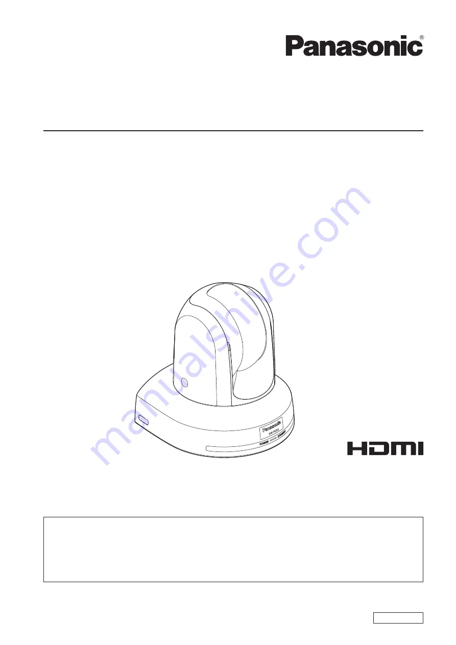
HD Integrated Camera

PGQX1222ZAA/C1(E)

M0912MS0 -FJ

ENGLISH

  How the Operating Instructions are configured

  <Basics>:

     The <Basics> describes the procedure for basic operation and installation. Before installing this unit, be 

sure to take the time to read through <Basics> to ensure that the unit will be installed correctly.

  <Operations and Settings> 

(this manual):

    This <Operations and Settings> describes how to operate the unit and how to establish its settings.


Model No. 

AW‑HE60HN


Model No. 

AW‑HE60SN


Model No. 

AW‑HE60HE


Model No. 

AW‑HE60SE

Summary of Contents for AW?HE60SE

Page 1: ... procedure for basic operation and installation Before installing this unit be sure to take the time to read through Basics to ensure that the unit will be installed correctly Operations and Settings this manual This Operations and Settings describes how to operate the unit and how to establish its settings Model No AW HE60HN Model No AW HE60SN Model No AW HE60HE Model No AW HE60SE ...

Page 2: ...right and licence Distributing copying disassembling reverse compiling reverse engineering and also exporting in violation of export laws of the software provided with this unit are expressly prohibited Abbreviations The following abbreviations are used in this manual p p Microsoft Windows 7 Professional SP1 32 64 bit is abbreviated to Windows 7 p p Microsoft Windows XP Professional SP3 and Micros...

Page 3: ...P655 35 Control exercised from the Multi Hybrid Control Panel AW RP555 37 Control exercised from the Remote Camera Controller AW RP50 39 Camera menu items 40 Setting the camera menu items 40 Top Menu screen 40 Camera screen when FullAuto is selected 41 Camera screen when Manual1 to 3 is selected 41 Contrast screen 42 Picture 1 2 screen 43 Picture 2 2 screen 44 16 axis color matrix 45 System screen...

Page 4: ... with the equivalent specifications Memory When using Windows 512 MB or more When using Microsoft Windows 7 1 GB 32 bits or 2 GB 64 bits or more When using Mac OS X 2 GB or more Network function 10BASE T or 100BASE TX port 1 Image display function Resolution 1024 768 pixels or more Color generation True Color 24 bits or more Supported operating system and Web browser Microsoft Windows 7 Profession...

Page 5: ...RE w wNetwork security As you will use this unit connected to a network your attention is called to the following security risks 1 Leakage or theft of information through this unit 2 Use of this unit for illegal operations by persons with malicious intent 3 Interference with or stoppage of this unit by persons with malicious intent It is your responsibility to take precautions such as those descri...

Page 6: ...e 65 if a message appears on the information bar of the browser p p When a Live screen is first displayed from the personal computer the screen on which to install ActiveX required to display the camera images appears Follow the on screen instructions to install the software p p If the installation screen is displayed every time the screen is switched even after ActiveX has been installed reboot t...

Page 7: ...ferences When continuing to shoot in the same circumstances there is no need to select another mode 5 Start shooting After shooting turn off the power of all the units and devices in the system p p If FullAuto has been selected as the setting for Scene on the camera menu for example all the auto settings will be turned on and manual operations will no longer be possible for some of the items Note ...

Page 8: ...n a signal matched by the remote control ID has been received and it blinks orange when a signal that is not matched by the remote control ID has been received When performing the operations using the controller When the AW RP655 or AW RP555 is connected 1 Set all the power switches of the units and devices connected in the system to ON p p This unit does not have a power switch When power is supp...

Page 9: ...The zoom position is stored using the setting established immediately before the power is turned off Notes When performing the operations using the controller When the AW RP655 or AW RP555 is connected 1 Set the OPERATE switch on the controller to OFF The power of all the cameras including the unit connected to the controller is turned off p p The unit s status display lamp now lights up orange 2 ...

Page 10: ...des scene files w wTypes of shooting modes This unit has four preset shooting modes each of which corresponds to a set of circumstances in which the subject will be shot Select the mode that satisfies the shooting conditions and suits your preferences The settings can be changed by menu operations p p The results of the white balance and other adjustments are stored in the memory separately by sho...

Page 11: ...ne FullAuto System Maintenance 3 Press the or button to bring the cursor to Camera 4 Press the button The Camera sub menu is displayed on the monitor Camera Scene FullAuto Contrast Level 0 Day Night Day Return 5 Press the or button to bring the cursor to Scene 6 Press the button The shooting mode blinks 7 Press the or button to select the shooting mode FullAuto Manual1 Manual2 or Manual3 to be use...

Page 12: ...t and press the OK button SCENE HALOGEN OK Key The scene names displayed on the LCD panel correlate with the scene files of the AW HE60 as shown below AW RP655 display AW HE60 scene file HALOGEN Manual1 FLUORESCENT Manual2 OUTDOOR Manual3 USER FullAuto 5 When the following message appears on the LCD panel press the MENU button twice to exit the menu mode OPEN CAMERA MENU OK Key When the AW RP555 i...

Page 13: ...d The lens focus control speed is also changed at the same time When performing the operations using the controller q qChanging the camera s direction Moving the camera toward the left or right panning Tilt the PAN TILT lever toward L or R Moving the camera up or down tilting Tilt the PAN TILT lever toward UP or DOWN Moving the camera diagonally Tilt the PAN TILT lever diagonally Returning the cam...

Page 14: ...and switch to ATW The camera menus are not displayed When color bar signals are output the camera menus are not displayed with composite signals To operate the camera menus with composite signals set the color bar display to OFF When performing the operations using the controller The unit does not move p p Select the unit to be operated by following the procedure below When the AW RP655 is connect...

Page 15: ...r tones of the entire screen p p It must be performed when using the unit for the first time or when the unit has not been used for a prolonged period p p It must be performed when the lighting conditions or brightness has changed p p Once the white balance has been attained no further adjustment is required provided that the unit is going to be used under the same conditions Black level master pe...

Page 16: ...ever Furthermore every time the SPEED button is pressed the speed of the focusing and other adjustments can be switched to fast or slow 3 If necessary press the EXT AF button to return the focus to the automatic adjustment When the AW RP555 is connected 1 Press the AF EXT button to switch the focus to manual adjustment 2 Adjust the focus manually by tilting the FOCUS lever Furthermore every time t...

Page 17: ...lly by turning the dial above the lit IRIS lamp whether it is the lamp of the PAN TILT lever or ZOOM lever 3 If necessary press the IRIS button several times and turn on its lamp to return the iris to the automatic adjustment When the AW RP555 is connected 1 Press the IRIS button to turn off its lamp and switch to manual adjustment 2 Turn the LEVEL dial of IRIS to adjust the iris manually The posi...

Page 18: ...d turn its lamp on The shutter speed set ahead of time is selected 2 If necessary press the SHUTTER button to turn its lamp off in order to return the shutter to the OFF setting q q How to set the shutter speed using the AW RP555 1 With the MEMORY button held down press the SHUTTER button The 1 to 5 and 6 to 10 buttons of PRESET blink alternately 2 Press one of the 1 to 8 buttons or the 10 buttons...

Page 19: ...onnected 1 Press the GAIN button to turn off its lamp and then switch to manual adjustment The preset gain increase amount is now selected For further details on the gain increase amount setting refer to the Operating Instructions of the AW RP655 2 If necessary press the GAIN button and turn on the button in order to return the gain to the automatic adjustment AGC When the AW RP555 is connected 1 ...

Page 20: ... p p If displacement occurs perform registration again p p While preset settings are being called it is not possible to perform manual operations such as panning tilting zooming or iris adjustments p p If when one set of preset settings has been called another set of preset settings is then called the first set of preset settings which have been called will take precedence Notes When performing th...

Page 21: ...ry settings cannot be registered in buttons whose lamps are off since they contain tracing memory settings 5 With the MEMORY button still held down press the button of the preset memory number in which the setting is to be registered q q Calling the settings of the preset memories 1 Set to the preset memory mode Press the TR PSET button to turn off its lamp 2 Press the button among the 1 to 50 but...

Page 22: ...t the focus iris gain and white balance if they need to be adjusted 2 Hold down the MEMORY button The buttons among the 1 to 10 buttons of PRESET in which settings can be registered now start blinking in sequence 3 With the MEMORY button still held down press the button of the preset memory number in which the setting is to be registered q q Calling the settings of the preset memories 1 Press the ...

Page 23: ...up procedure will be completed simply by selecting them using the camera menus or web settings or by pressing the buttons on the controller provided that they are going to be used under the same conditions as the ones established when the values were set There is no need to set it again p p Once a new setting is entered the previous setting will be erased Use the two memories to store settings cor...

Page 24: ...e auto white balance adjustment AWB cannot be used Notes When performing the operations using the controller When the AW RP655 or AW RP555 is connected 1 Shoot a white subject such as a white wall or handkerchief so that it fills the screen p p Do not shoot shiny or very bright objects 2 Press the A button or B button of WHITE BAL to select AWB A or AWB B for the white balance The selected button ...

Page 25: ...ce adjustment is set to ATW the white balance continues to be adjusted automatically all the time and it is automatically corrected even when the light source or color temperature has changed to produce completely natural pictures This function works when ATW is selected instead of AWB A or AWB B by following the steps for Automatic adjustment in White balance adjustment page 23 p p ATW might not ...

Page 26: ...Tone Mode Off DNR High Return 4 Press the or button to bring the cursor to AWB Mode 5 Press the button AWB Mode starts blinking 6 Press the or button to change the AWB mode to be used to AWB A or AWB B and press the button to enter the selection 7 Press the or button to bring the cursor to R Gain or B Gain 8 Press the button to make the R Gain or B Gain value blink 9 Press the or button to change ...

Page 27: ...y following the procedure in How to select the shooting mode page 11 under Selecting the shooting modes scene files 4 Press the or button to bring the cursor to Picture 5 Press the button The Picture 1 2 sub menu is displayed Picture 1 2 Chroma Level 0 AWB Mode AWB A R Gain 0 B Gain 0 Detail High Flesh Tone Mode Off DNR High Return 6 Press the or button to move to the Picture 2 2 sub menu and brin...

Page 28: ... displayed on the LCD panel 4 Turn the jog dial main and adjust the black level to 0 035 V 5 If necessary adjust the iris automatically Press the IRIS button several times to turn on its lamp When the AW RP555 is connected 1 Press the IRIS button several times to turn off its lamp Set the iris to the manual MANU mode 2 Turn the LEVEL dial of IRIS to stop down the lens iris 3 Follow the operation s...

Page 29: ...rforming the operations using the wireless remote control 1 Follow the operation steps in Basic operations page 34 to display the Top Menu 2 Press the or button to bring the cursor to System Top Menu Camera Scene FullAuto System Maintenance 3 Press the button The System sub menu is displayed System Genlock Output Other Return 4 Press the or button to bring the cursor to Genlock and press the butto...

Page 30: ... button The mode is switched to the color bar display 2 Follow the operation steps in Basic operations page 34 to display the Top Menu 3 Press the or button to bring the cursor to System Top Menu Camera Scene FullAuto System Maintenance 4 Press the button The System sub menu is displayed System Genlock Output Other Return 5 Press the or button to bring the cursor to Genlock and press the button Th...

Page 31: ...ng the operations using the controller These operations can be performed using the camera menus by following the operation steps in Basic operations pages 32 to 39 To switch between BAR color bar display and CAM camera pictures press the MODE or BAR CAM button ...

Page 32: ...bstitute controller for wireless remote control when reading the basic operations Also refer to the Operating Instructions of the controller Table of operations Camera menu operation Wireless remote control Controller AW RP655 AW RP555 AW RP50 Selecting the unit to be operated Press the CAM1 CAM2 CAM3 or CAM4 button Press one of the 1 to 5 buttons of CONTROL PREVIEW MONITOR OUT SEL Press one of th...

Page 33: ...hange the setting 3 Press the F1 dial to enter the setting and stop the blinking Canceling the setting change While the setting is blinking press the MENU button quickly for less than 2 seconds While the setting is blinking press the jog dial R While the setting is blinking press the MENU button Exiting the camera menu operations Press the MENU button for 2 seconds Press the MENU button or R B GAI...

Page 34: ...splayed Some sub menu items have a sub menu of their own 5 Press the or button to bring the cursor to the item to be set Each time the or button is pressed the cursor moves The cursor can be moved in the same way using the and buttons With the cursor at the Return position press the button to return to the previous menu 6 Press the button The value of the item to be set starts blinking 7 Press the...

Page 35: ... an ABC function This is used to acquire the statuses of the camera and synchronize the data 3 Each time the MODE button is pressed the setting is switched between CAM and BAR The MODE button lights up at the BAR setting Jog dial R When the LCD is in the camera menu mode Press the jog dial R to cancel the setting change When the LCD is in the gain adjustment mode Adjust the B GAIN setting 150 to 1...

Page 36: ...play AW HE60 scene file HALOGEN Manual1 FLUORESCENT Manual2 OUTDOOR Manual3 USER FullAuto 5 When the following message appears on the LCD panel press the OK button again OPEN CAMERA MENU OK Key The camera menu of the AW HE60 is displayed on the monitor 6 Turn the jog dial main to select camera menu items of the AW HE60 and change the data Turn the jog dial main when the cursor is to be moved up or...

Page 37: ...as shown below ON LED lights OFF LED off GAIN button MANU L LED MANU H LED AUTO ON OFF OFF 0dB OFF OFF OFF LOW OFF ON OFF HIGH OFF OFF ON Others OFF ON ON Shutter mode selection Each time this button is pressed one of the shutter modes set by the controller or shutter OFF is selected The SHUTTER button lights up in all modes except shutter OFF The shutter mode settings established by the PRESET bu...

Page 38: ... If the YES button is pressed the selection item moves up if the NO button is pressed it moves down 4 Press the ITEM button The value of the item to be set starts blinking 5 Press the YES or NO button to change the setting 6 After deciding on the setting press the ITEM button The value of the item to be set is entered and it stops blinking 7 Press the MENU button for 2 seconds to exit the camera m...

Page 39: ... to move the cursor up or down on the camera menu or change the setting Press it when moving to the menu at the next lower hierarchical level or changing a setting at the very bottom hierarchical level For selecting the cameras to be operated q qProcedure for camera menu operation AW RP50 1 Press one of the CAMERA STATUS SELECTION buttons to select the unit which is to be operated 2 Press the CAME...

Page 40: ...st hierarchical level whereas and indicate that the second hierarchical level is now displayed Menu items accompanied by a mark indicate data which is stored on a scene by scene basis menu items accompanied by a mark indicate data which is stored together for one camera regardless of the scenes w wTop Menu screen Top Menu Camera Scene FullAuto System Maintenance Camera Select this to open the came...

Page 41: ...the mode concerned is displayed Contrast Level 5 to 5 Set here is the contrast level when the image brightness is adjusted Day Night Day Night This is used to select normal shooting or low light shooting by exposing the subjects to infrared rays Day Normal shooting Night Low light shooting In the night mode Black and white images are output The lens iris is forcibly set to open In the night mode t...

Page 42: ...peeds that can be set are listed below When 59 94 Hz has been set as the unit s frequency When Step is selected as the Shutter Mode When Synchro is selected as the Shutter Mode 1 100 1 250 1 500 1 1000 1 2000 1 4000 1 10000 60 24 Hz to max 646 21 Hz 255 steps When 50 Hz has been set as the unit s frequency When Step is selected as the Shutter Mode When Synchro is selected as the Shutter Mode 1 120...

Page 43: ...s executed the R Gain and B Gain values are returned to 0 p p When AWB A or AWB B is selected as the AWB Mode setting the R Gain and B Gain adjustment values can be stored in the two memories A and B p p When new values are set the previous values are erased Use each of the memories for a different purpose in accordance with the shooting conditions p p In terms of registering values in the preset ...

Page 44: ...vel The item s setting takes effect when Off has been selected as the DRS setting and Normal as the Gamma Type setting When Low is set the images appear sedate and composed The resulting gamma curve has a gentle gradient in the low brightness areas and the contrast is sharper Conversely when High is set the tonal range in the dark area is expanded so that the images take on a lighter tone The resu...

Page 45: ...t Normal EBU NTSC User The preset color matrix data is loaded and the saturation and phase are compensated accordingly When User is selected the saturation and phase can be finely adjusted using the 16 axis color matrix Axis01 to Axis16 90 180 270 0 22 5 45 67 5 112 5 135 157 5 202 5 225 247 5 292 5 315 337 5 Axis 1 Axis 2 Axis 3 Axis 4 Axis 5 Axis 6 Axis 7 Axis 8 Axis 9 Axis 10 Axis 11 Axis 12 Ax...

Page 46: ...e other functions Return Use this to return to the previous menu w wGenlock screen AW HE60S only Genlock Horizontal Phase 0 Subcarrier Phase Coarse 90 Fine 0 H Phase SC Fine Step 1 Return Horizontal Phase 206 to 49 This is used to adjust the horizontal phase during genlock Subcarrier Phase Coarse 0 to 315 This is used to adjust coarsely the color phase during genlock This setting is valid for the ...

Page 47: ...is selected for the color bar the mode is fixed to Squeeze If the color bar display is turned ON or OFF when the SideCut or LetterBox setting has been selected the images will break up on the display for several dozen seconds HDMI Color AW HE60H only RGB NOR RGB ENH YCbCr422 YCbCr444 Set here is the HDMI color output When an HDMI monitor is used use YCbCr422 under normal circumstances In cases whe...

Page 48: ...d Format Set screen Format 1080 59 94i Set The format to be set is displayed within the parentheses on the screen When the cursor is moved to CANCEL on the format change check screen and the setting is entered the Format unchanged screen appears for 5 seconds the format is left unchanged and the display returns to the Output screen Attention screen Attention Format 1080 59 94i If you select O K Th...

Page 49: ...Zoom Disable Enable Enable or Disable is set here for the digital zoom function If zooming is performed toward the Tele end beyond the maximum position when Enable has been selected the digital zoom can be operated continuously Zooming will stop temporarily at the position where the optical zoom and digital zoom are switched Stop zooming at this position and then proceed with zooming again When th...

Page 50: ... is received by a command or contact When the tally signal is released the original OSD menu displays are restored OSD Status Off On Off or On is set here for the status display which appears during AWB operations Wireless Control Disable Enable Enable or Disable is set here for operations conducted from the wireless remote control The operations are enabled when the unit s power is turned on from...

Page 51: ... Concerning initialization on page 52 Return Use this to return to the previous menu w wFirmware Version screen Firmware Version CPU Software Camera Main V01 00 Pan Tilt V01 00 Network V01 00 PLD Camera V01 00 Output V01 00 EEPROM V01 00 Return CPU Software Camera Main This is selected to display the software version of the camera unit CPU Software Pan Tilt This is selected to display the software...

Page 52: ... Maintenance screen the Initialize screen appears Initialize screen Initialize Do you want to initialize Menu settings CANCEL O K Return When the cursor is moved to O K on the Initialize screen and the setting is entered the Menu settings initialized screen is displayed for 5 seconds and the camera settings are restored to the settings which were established when the camera was purchased Camera me...

Page 53: ... 12dB 18dB Picture Picture 1 2 Chroma Level 0 3 to 3 AWB Mode AWB A ATW AWB A AWB B R Gain 0 30 to 30 B Gain 0 30 to 30 Detail High Off Low High Flesh Tone Mode Off Off Low High DNR High Off Low High Picture 2 2 Pedestal 0 10 to 10 DRS Off Off Low High Gamma Type Normal Off Normal Cinema Gamma Level Mid Low Mid High Back Light COMP Off Off On Day Night Day Day Day Night Color Matrix 1 3 Matrix Sel...

Page 54: ...20 50p 576 50p 576 50i 1080 25PsF AW HE60S 1080 50i 720 50p 576 50i 1080 25PsF Down CONV Mode LetterBox Squeeze SideCut LetterBox HDMI Color AW HE60H only YCbCr422 RGB NOR RGB ENH YCbCr422 YCbCr444 Other Other 1 2 Install Position Desktop Desktop Hanging Preset Speed 10 1 to 30 Preset Scope Mode A Mode A Mode B Mode C Digital Zoom Disable Disable Enable Speed With Zoom POS On Off On Focus Mode Aut...

Page 55: ...f private addresses 192 168 0 0 to 192 168 0 255 p p If the controller and web browser are being used at the same time the content selected using the controller may not be reflected on the web browser display When using both the controller and web browser be absolutely sure to check the settings using the controller or camera menu Notes For details of the required personal computer environment ref...

Page 56: ...Safari 2 Input http 192 168 0 10 in the address box of the web browser If the IP address has been changed input http changed IP address instead If HTTP port page 89 has been changed from its initial setting of 80 input http camera s IP address port number Example If the HTTP port number has been set to 8080 http 192 168 0 10 8080 3 Press the Enter key A Live screen is displayed The Live screen has...

Page 57: ...ed The initial settings for the user name and password are given below User name admin Password 12345 Notes p p While the initial settings remain used for the user name and password a message prompting the user to change the user name and password is displayed after authorization In order to ensure security the password for the user name of admin must be changed without fail It is also recommended...

Page 58: ...f time using the multi screen page 83 it is possible to view a multiple number of IP videos on a single screen Multi display mode Compression button Compression H 264 images are displayed The H 264 button is enabled when the H 264 transmission setting of H 264 image settings on the Video over IP is On see page 67 JPEG images are displayed Image Capture Size button Image Capture Size The IP video i...

Page 59: ...andby mode In the standby mode all the buttons on the Live screen except for the Setup button Multi screen list box Power ON button Standby button and Op Lock button are disabled Similarly on the Setup screen it is not possible to select Image Position or System under the Image button or Backup under the Maintenance button p p If Power ON or Standby is selected too quickly the status selected and ...

Page 60: ...ttings only JPEG images will appear H 264 images will not appear p p When On is selected as the H 264 transmission setting the maximum speed at which the JPEG images are refreshed is limited to 15 fps regardless of whether H 264 images are being displayed p p The speed at which the JPEG images are refreshed may be reduced depending on the network environment performance of the personal computer us...

Page 61: ...conversely when the right half of the pad is clicked the focus is adjusted in the Far direction The zooming can also be adjusted by operating the mouse wheel p p When the mouse is used for dragging and dropping from the control pad area to a position outside this area the panning tilting and other operations will not stop In a case like this click the control pad area to stop these operations Note...

Page 62: ...sites window input http unit s IP address in the Add this website to the zone field 4 Remove the check from Require server verification https for all sites in this zone and click the Add button 5 Check that the unit s IP address has been added to the Websites field and click the Close button 6 Click the OK button Notes Full screen display This function enables the full screen display of images dis...

Page 63: ...4 cameras up to four groups of cameras a total of 16 cameras can be registered see page 83 Multi screen consisting of 4 sub screens Multi screen consisting of 16 sub screens Multi Screen list box Multi screen The Live screen display method is selected here The IP videos of the connected camera are displayed When the cameras for multi screen display have been set ahead of time using the multi scree...

Page 64: ...n is pressed the login screen shown below is displayed The initial settings for the user name and password are given below User name admin Password 12345 When the OK button is clicked after inputting the values the screen shown below is displayed Click the OK button p p While the initial settings remain used for the user name and password a message prompting the user to change the user name and pa...

Page 65: ...isplayed p p Half size numeric characters 0123456789 p p Half size alphabetical characters upper and lower cases ABCDEFGHIJKLMNOPQRSTUVWXYZ abcdefghijklmnopqrstuvwxyz p p Symbols _ Automatic installation of viewer software On Off Initial setting On One of the following settings is selected for the automatic installation of the plug in viewer software On The plug in viewer software is automatically...

Page 66: ...Video over IP Monitoring mode IP Select this when using the IP video output VIDEO OUT Select this when using VIDEO OUT p p When using the IP video output the SDI OUT HDMI OUT and component OUT signals are output but the VIDEO OUT signals are not output Note 16 9 resize On The IP videos transmitted in the 4 3 aspect ratio are resized to the 16 9 aspect ratio Off The IP videos are not resized to the...

Page 67: ... Whether to transmit the H 264 images is set here using On or Off H 264 transmission can be used by Windows only On H 264 images are transmitted Off H 264 images are not transmitted p p When On has been selected as the H 264 transmission setting both H 264 images and JPEG images can be displayed on the live screen p p When On has been selected as the H 264 transmission setting the image refresh in...

Page 68: ... frame rate may become slower Notes Max bit rate per client 64kbps 128kbps 256kbps 384kbps 512kbps 768kbps 1024kbps 1536kbps 2048kbps 3072kbps 4096kbps Unlimited Initial setting 4096kbps The H 264 bit rate per client is selected here p p Unlimited can be selected only when Frame rate has been selected as the Transmission priority setting p p The H 264 bit rate is linked to the Bandwidth control bi...

Page 69: ... port MANUAL With this setting up to 14 users can access one camera at the same time When sending images from the camera Unicast port must be set manually When sending H 264 images over the internet always use the same communication enabled port number that is set in the broadband router hereafter the router For further details refer to the operating instructions of the router used p p When Unicas...

Page 70: ...onnected camera will be displayed While the tally lamp is on the area frame will turn red When the tally lamp is off the display area will return to normal Image adjust When the Setup button is clicked the Image adjust screen is displayed Preset position When the Setup button is clicked the Preset position setting screen is displayed ...

Page 71: ...71 Controls and settings from web screen continued Image adjust screen When Scene is set to FullAuto When Scene is set to Manual1 to 3 ...

Page 72: ...s do not become blurred easily but the images will be darker Off The shutter is set to OFF so that it cannot be tripped Step The step shutter is set the steps can be changed Synchro The synchro shutter is set the setting can be changed continuously The shutter speeds that can be set are listed below When 59 94 Hz has been set as the unit s frequency When Step is selected as the Shutter Mode When S...

Page 73: ... as the Preset Scope setting the R Gain and B Gain settings are returned to 0 p p When ATW has been selected as the AWB Mode setting the R Gain and B Gain cannot be adjusted Notes Detail Off Low High The image detail image sharpness is adjusted here When Low or High is selected the detail is enhanced Flesh Tone Mode Off Low High Set here is the flesh tone mode for displaying the subjects skin so t...

Page 74: ...red rays Day Normal shooting Night Low light shooting p p In the night mode Black and white images are output The lens iris is forcibly set to open In the night mode the auto white balance adjustment AWB cannot be used Color Matrix Color Matrix Normal EBU NTSC User The preset color matrix data is loaded and the saturation and phase are compensated accordingly When User is selected the saturation a...

Page 75: ...en is displayed when User is selected as the Color Matrix setting on the Image adjust screen and the Setup button is clicked Axis 01 to Axis 16 Saturation 127 to 127 The saturation of Axis 01 to Axis 16 can be finely adjusted Axis 01 to Axis 16 Phase 127 to 127 The phase of Axis 01 to Axis 16 can be finely adjusted ...

Page 76: ... if Home has been selected on the pull down menu This is used to delete the preset position setting which is currently being selected It does not function if Home has been selected on the pull down menu Pan Tilt Lens Control Zoom Use this to adjust the zoom magnification in the Wide direction Use this to adjust the zoom magnification to 1 0 Use this to adjust the zoom magnification in the Tele dir...

Page 77: ...e focus is adjusted in the Far direction The zooming can also be adjusted by operating the mouse wheel p p When the mouse is used for dragging and dropping from the control pad area to a position outside this area the panning tilting and other operations will not stop In a case like this click the control pad area to stop these operations Note Speed Use this to select the speed at which the pan ti...

Page 78: ... white balance adjustment value Mode B Pan Tilt Zoom including digital zoom Focus Iris Mode C Pan Tilt Zoom including digital zoom Focus Limitation Setting This establishes the up down left and right limit settings of the pan tilt head First move the pan tilt head to the position where the limit is to be set and press the corresponding button below to set the direction up down left or right in whi...

Page 79: ...0S only Horizontal Phase 206 to 49 This is used to adjust the horizontal phase during genlock Subcarrier Phase Coarse 0 to 315 This is used to adjust coarsely the color phase during genlock This setting is valid for the VBS signal output Subcarrier Phase Fine 127 to 127 This is used to adjust finely the color phase during genlock This setting is valid for the VBS signal output ...

Page 80: ... OFF when the SideCut or LetterBox setting has been selected the images will break up on the display for several dozen seconds HDMI Color AW HE60H only RGB NOR RGB ENH YCbCr422 YCbCr444 Set here is the HDMI color output When an HDMI monitor is used use YCbCr422 under normal circumstances In cases where for instance HDMI RGB signals are converted and output to a DVI monitor the settings required wi...

Page 81: ...performed toward the Tele end beyond the maximum position when Enable has been selected the digital zoom can be operated continuously Zooming will stop temporarily at the position where the optical zoom and digital zoom are switched Stop zooming at this position and then proceed with zooming again When the setting is changed to Disable while already in the digital zoom region the zoom will automat...

Page 82: ...tting items listed above Off ByBrowser If a menu has been opened from the browser screen the camera menus and statuses are not displayed on the output images for which this setting is established p p Even if the display has been set to the off position the camera menus will still be displayed for one minute whenever the power of the unit is turned on Note OSD Off With Tally Off On This is used to ...

Page 83: ... cameras a total of 16 cameras can be registered Input as follows if the HTTP port number of the camera whose images are to be displayed has been changed Example of input Address 192 168 0 10 8080 p p When the host name is to be set the DNS setting of the personal computer that will display the multi screen is required see page 89 Camera title 0 to 20 half size characters Initial setting blank Inp...

Page 84: ...ing using the Set button p p If On has been selected as the User auth setting control will no longer be exercised from the AW RP50 remote camera controller Use Host auth page 85 if the AW RP50 is to be used Access level Initial setting 3 Live only Select one of the following settings as the user access level Enter the setting using the Set button 1 Administrator This access level allows the user t...

Page 85: ...g the personal computers from 192 168 0 1 to 192 168 0 254 will be able to access the camera at the 2 Camera control access level p p When an already registered IP address is input and the Set button is clicked the host information will be overwritten Access level Initial setting 3 Live only Select one of the following settings as the host access level 1 Administrator 2 Camera control 3 Live only ...

Page 86: ...tion is input here Destination IP address 2 Initial setting blank The IP address of the second send destination is input here Stream type Initial setting JPEG JPEG or H 264 is set as the stream type here JPEG JPEG images are sent H 264 H 264 images are sent Refresh interval 1fps 2fps 3fps 5fps 6fps 10fps 15fps 30fps Initial setting 1fps The speed at which the images are to be refreshed is set here...

Page 87: ...rver is used as the unit s standard time NTP server address 1 to 128 half size characters Initial setting blank The host name or IP address of the NTP server is input here p p To input the NTP server address host name the DNS setting page 89 must be selected on the Network screen of the Network settings Note NTP port 1 to 65535 Initial setting 123 The port number of the NTP server is input here Ti...

Page 88: ... same IP address cannot be used by personal computers without the DHCP function or by other network cameras For details on the server settings consult your network administrator IP address Initial setting 192 168 0 10 Input the unit s IP address here when the DHCP function is not going to be used Input an address that will not duplicate an existing IP address which has been set for a personal comp...

Page 89: ... 1 to 65535 Initial setting 80 The port number is allocated here separately The following port numbers are used by the unit therefore cannot be used Port numbers already used 20 21 23 25 42 53 67 68 69 110 123 161 162 554 995 10669 10670 59000 to 59999 60000 to 61000 Line speed Initial setting Auto Select one of the following data line speeds Normally it is recommended that the Auto default settin...

Page 90: ...nity name which is to be monitored p p When using the SNMP function be absolutely sure to input the community name This function cannot be used if the community name field is left blank Note System name 0 to 32 half size characters Initial setting blank Input here the system name for controlling the unit using the SNMP function Location 0 to 32 half size characters Initial setting blank Input here...

Page 91: ...hundred system logs can be stored in the unit s internal memory When this maximum number has been exceeded the old logs are overwritten successively by the new logs The logs are cleared when the unit s power is turned off No The running numbers of the system logs are displayed here Time date The times and dates when the logs were generated are displayed here The 24 hour system is used to display t...

Page 92: ...erial no The unit s serial number is displayed here Firmware version CPU Software Camera Main This is selected to display the software version of the camera unit CPU Software Pan Tilt This is selected to display the software version of the pan tilt unit CPU Software Network This is selected to display the software version of the network unit PLD Camera This is selected to display the PLD version o...

Page 93: ...rade the software versions from the personal computer in the same network LAN as the unit whose firmware version is to be updated Note Status The current status of the unit is displayed here p p After the Execute button has been pressed it will take about one minute with the Camera Main software or about 3 minutes with the Network software for the progress bar that indicates the progress made in t...

Page 94: ...ngs under Setup Image Image Position ImageAdjust p p All the settings except Format and Frequency under Setup Image System p p All the settings under Setup Multi screen p p All the settings under Setup User mng p p All the settings under Setup Server p p All the settings under Setup Network SNMP p p Setup Maintenance System log system log history When the initialization operation is started no ope...

Page 95: ...al If a setting file with the same filename already exists a number is automatically allocated and added to the end of the filename and the downloaded file is saved under this name The setting files have the txt extension Uploading files which have this extension is not a problem Setting files which have been downloaded open automatically If the check is removed from Open safe files after download...

Page 96: ...ormal 0 Super fine 1 Fine 2 3 4 5 Normal 6 7 8 9 Low H 264 H 264 transmission On On Off Internet mode over HTTP Off On Off Image capture size VGA VGA QVGA Transmission priority Frame rate Constant bit rate Frame rate Frame rate 30fps 1fps 3fps 5fps 7 5fps 10fps 15fps 20fps 30fps Max bit rate per client 4096kbps 64kbps 128kbps 256kbps 384kbps 512kbps 768kbps 1024kbps 1536kbps 2048kbps 3072kbps 4096...

Page 97: ...xis 05 Saturation 0 127 to 127 Phase 0 127 to 127 Axis 06 Saturation 0 127 to 127 Phase 0 127 to 127 Axis 07 Saturation 0 127 to 127 Phase 0 127 to 127 Axis 08 Saturation 0 127 to 127 Phase 0 127 to 127 Axis 09 Saturation 0 127 to 127 Phase 0 127 to 127 Axis 10 Saturation 0 127 to 127 Phase 0 127 to 127 Axis 11 Saturation 0 127 to 127 Phase 0 127 to 127 Axis 12 Saturation 0 127 to 127 Phase 0 127 ...

Page 98: ... HE60HE AW HE60SE AW HE60HMC AW HE60SMC 50Hz PAL 59 94Hz NTSC 50Hz PAL Other Install Position Desktop Desktop Hanging Preset Speed 10 1 to 30 Preset Scope Mode A Mode A Mode B Mode C Digital Zoom Disable Disable Enable Speed With Zoom POS On Off On Focus Mode Auto Auto Manual Focus ADJ With PTZ Off On Tally Enable Enable Disable Enable OSD Mix HDMI COMP AW HE60H SDI COMP AW HE60S Off ByBrowser Off...

Page 99: ... Off On Off IP address 192 168 0 10 Subnet mask 255 255 255 0 Default gateway 192 168 0 1 DNS Manual Auto Manual Primary server address Secondary server address HTTP port 80 1 to 65535 Line speed Auto Auto 100 M Full 100 M Half 10 M Full 10M Half Bandwidth control bit rate Unlimited Unlimited 64kbps 128kbps 256kbps 384kbps 512kbps 768kbps 1024kbps 2048kbps 4096kbps 8192kbps Easy IP Setup accommoda...

Page 100: ... Pan Tilt Zoom Preset Iris Focus Camera menu OSD menu operation p p If the mobile terminal does not support the character code UTF 8 the characters cannot be displayed properly p p The maximum number of Android terminals which can be connected to the unit at the same time is one Note 1 Input http IP address mobile 1 using the mobile terminal and press the enter button The unit s images will now be...

Page 101: ...r selecting the resolution are displayed on the screen The characters are displayed in green for the resolution button which is currently selected If Off is selected as the 16 9 resize setting among the Video over IP the unit s images are displayed using the aspect ratio of 4 3 If On is selected as the 16 9 resize setting the unit s images are displayed using the aspect ratio of 16 9 see page 66 T...

Page 102: ...utton is pressed the buttons for performing the focusing operations are displayed on the screen Use this to switch between auto and manual focusing At the auto setting focusing is performed the focal point is adjusted automatically At the auto setting the button label turns green When this is pressed while the focus is being adjusted manually the focus will be temporarily adjusted automatically It...

Page 103: ... administrator or user name and the password Depending on the mobile terminal it may be necessary to input the password each time the screen changes p p If the User auth page 84 setting has been changed to On from a personal computer while the mobile terminal screen is displayed it may not be possible to refresh the mobile terminal screen In a case like this first close the web browser which is ru...

Page 104: ...l error Undefined error p p A problem has occurred in the NTP function Check the NTP settings again Successful NTP based time synchronization NTP update succeeded p p The time has been updated successfully Login related displays Category Display Description of error Login User name or IP address p p If user authorization has been set the name of the user who has logged onto the unit is displayed p...

Page 105: ... which the user does not wish to be shot The positions of four limiters namely the upper lower left most and right most limits of the travel range can be set Once they have been set the positions will not be lost even after the power has been turned off The limiters can be set or released both by the wireless remote control and controller or web setting screen Whatever was set or released last tak...

Page 106: ...ion which will serve as the upper limit Next perform the steps in Basic limiter operations Press the MENU button quickly and then press the button for 2 seconds while holding down the PRESET button p p Setting the lower limit position of the movement range Press the or button of the wireless remote control to turn the unit as far as the position which will serve as the lower limit Next perform the...

Page 107: ...d then press the button for 2 seconds while holding down the PRESET button p p Releasing the left most limit position of the movement range Perform the steps in Basic limiter operations Press the MENU button quickly and then press the button for 2 seconds while holding down the PRESET button p p Releasing the right most limit position of the movement range Perform the steps in Basic limiter operat...

Page 108: ...ode is established In this mode the unit s functions are shut down and then the unit is returned to its regular status in about 30 seconds after it has been started up again or the initial setting operation is performed When the unit has detected trouble again the trouble triggered safe mode will be established again p p The output of pictures might be suspended when the safe mode is established I...

Page 109: ...t the recommended specifications of a personal computer In case there are no descriptions of Windows 7 refer to the following CPU Intel CoreTM 2 Duo 2 4 GHz or faster Memory 1 GB or more Network interface 10BASE T or 100BASE TX 1 port Monitor 1024 768 pixels or more 24 bit True color or better OS and web browser Windows 7 Professional SP1 64 bit 1 Windows 7 Professional SP1 32 bit 1 Windows Intern...

Page 110: ...ons on the Tools menu 2 Click the Security tab Then select the Trusted sites Refer to the screenshot 3 Select Low for Security level for this zone If the lower setting is selected the security level of personal computer will go down 4 Click the Sites button to open the Trusted sites window 5 Enter the IP address in the textbox Add this website to the zone and click the Add button Note Make sure Re...

Page 111: ...d then click the Change settings button Check Internet Explorer or EasyIpSetup Refer to the screenshot 4 Click the OK button Symptom 3 p p When starting the Easy IP Setup Software a message is displayed to request the password of administrator p p When exiting the Easy IP Setup Software the message This program might not have installed correctly is displayed Solution Turn off User Account Control ...

Page 112: ...fault scale 1 Right click on the desktop 2 Click Personalize 3 Click Display 4 Select Smaller 100 default for the character size of the screenshot click the Apply button and reboot the personal computer Refer to the screenshot q qRestrictions Restriction 1 When two browser windows are open and one is being displayed on another The back window may come to the front when the mouse pointer is placed ...

Page 113: ... click Tools on the menu bar 2 Click Compatibility View Settings 3 Remove the check from Display all websites in Compatibility View and click the Close button Refer to the screenshot Symptom 6 p p Network disconnection occurs when the personal computer enters the sleep mode Solution After canceling the sleep mode reload the screen as necessary Symptom 7 p p Characters such as a file name cannot be...

Page 114: ...k Include local directory path when uploading files to a server to activate the setting Refer to the screenshot Symptom 9 p p The Program Compatibility Assistant is displayed after exiting the Easy IP Setup Software Refer to the screenshot Solution This symptom happens only when the software has been used for the first time Select This program installed correctly q qRestrictions Restriction 1 On t...

Page 115: ... Contrast Mode 42 72 Contrast screen 42 Control pad and its buttons 61 77 M M CPU Software Camera Main 51 92 Network 51 92 Pan Tilt 51 92 x x D M M Day Night 41 44 74 M M Default gateway 89 M M Default Gateway 52 Default reset screen 94 M M Destination IP address 1 86 M M Destination IP address 2 86 M M Detail 43 73 M M DHCP 88 M M Digital Zoom 49 81 M M DNR 43 73 M M DNS 89 M M Down CONV Mode 47 ...

Page 116: ... setup screen 83 x x N Network 88 Network screen 88 No 91 M M NTP port 87 NTP screen 87 M M NTP server address 87 x x O Op Lock 59 OSD Menu Operation 59 M M OSD Mix Browser Video 50 82 HDMI COMP 50 82 SDI COMP 50 82 M M OSD Off With Tally 50 82 M M OSD Status 50 82 M M Other 46 81 Other 1 2 screen 49 Other 2 2 screen 50 M M Output 46 80 Output screen 47 x x P M M Pan Tilt 100 M M Pan Tilt Lens Con...

Page 117: ...0 System log screen 91 M M System name 90 System screen 46 79 x x T M M Tally Enable 50 81 M M Tally lamp lighting status displays 103 M M Time adjustment 87 M M Time adjustment interval 87 Time date 91 M M Time zone 87 M M Top Menu 40 Top Menu screen 40 M M Transmission priority 68 M M Transmission type 69 x x U M M Unicast port 69 M M Upload 95 M M User auth 84 User auth screen 84 M M User check...

Page 118: ...Web Site http panasonic net Panasonic Corporation 2012 ...

Reviews: