68
3. Basic operations
Adjusting the rotation angle
On the PinP1 menu (or PinP2 menu), turn [F1] to display the Rotation sub menu.
Either operate the positioner and rotary encoder [Z] or turn [F2], [F3] and [F4] to set the X rotation, Y rotation
and Z rotation.
<Menu
display>
PinP1 5|X |Y |Z |
Rotation| 0| 0| 0|
-360
|
+360
-360
|
+360
-360
|
+360
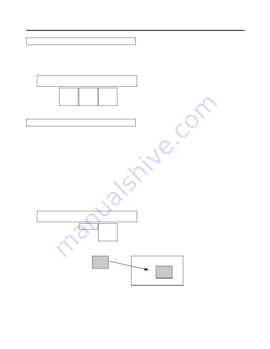
Select the dot by dot mode
When the system is set to the HD mode and an SD format image is to be used for the PinP material, the images
can be combined in the dot by dot mode (actual-size images).
In this mode, the SD format image will not be up-converted so image deterioration can be prevented.
When “100.00” has been selected as the Size item setting on the Position sub menu, the size used for the
combination will be the same number of lines as the SD format image.
Refer to “3-5-5. PinP adjustments”.
Press the [INPUT] button to light its indicator and display the INPUT menu.
Refer to “2-1-5. LCD menu area”.
Turn [F1] to display the INPUT XX sub menu.
(X: IN1 to IN16, A1, A2, B1, B2)
Select the PinP material input for X.
Turn [F2] to display the third menu of FS.
<Menu
display>
INPUT XX|FS |FS |Mode↓ |
| 1/15 | On|
Normal|
Off DbyD
UC
Auto
Turn [F4] to select DbyD using the Mode item, and press the [F4] switch to enter the selection.
SD
HD
SD
PinP material
PinP combined image


