


49
Lock Registration Phase
MF-Admin Server is required to complete all the tasks in this phase. Please follow the
MF-Admin Server & MP100 Installation Guide
to install MF-Admin Server.
MF-Admin Server is a web-based application with access controlled by login id and
password. A newly installed MF-Admin Server has an admin user with login id = alzk,
password = alzk. You may use this account to access all the functions in MF-Admin but
we recommend you create another ids for all the users who need to access MF-Admin.
Please check
MF-Admin Server User Guide
to see how to create users. The default
admin user alzk can not be removed. Change the password of alzk immediately is
recommended to secure the account. Please check
MF-Admin Server User Guide
to
see how to change alzk password.
To better illustrate all the steps, we will use a SIMPLE example project to describe how
to complete all the steps.
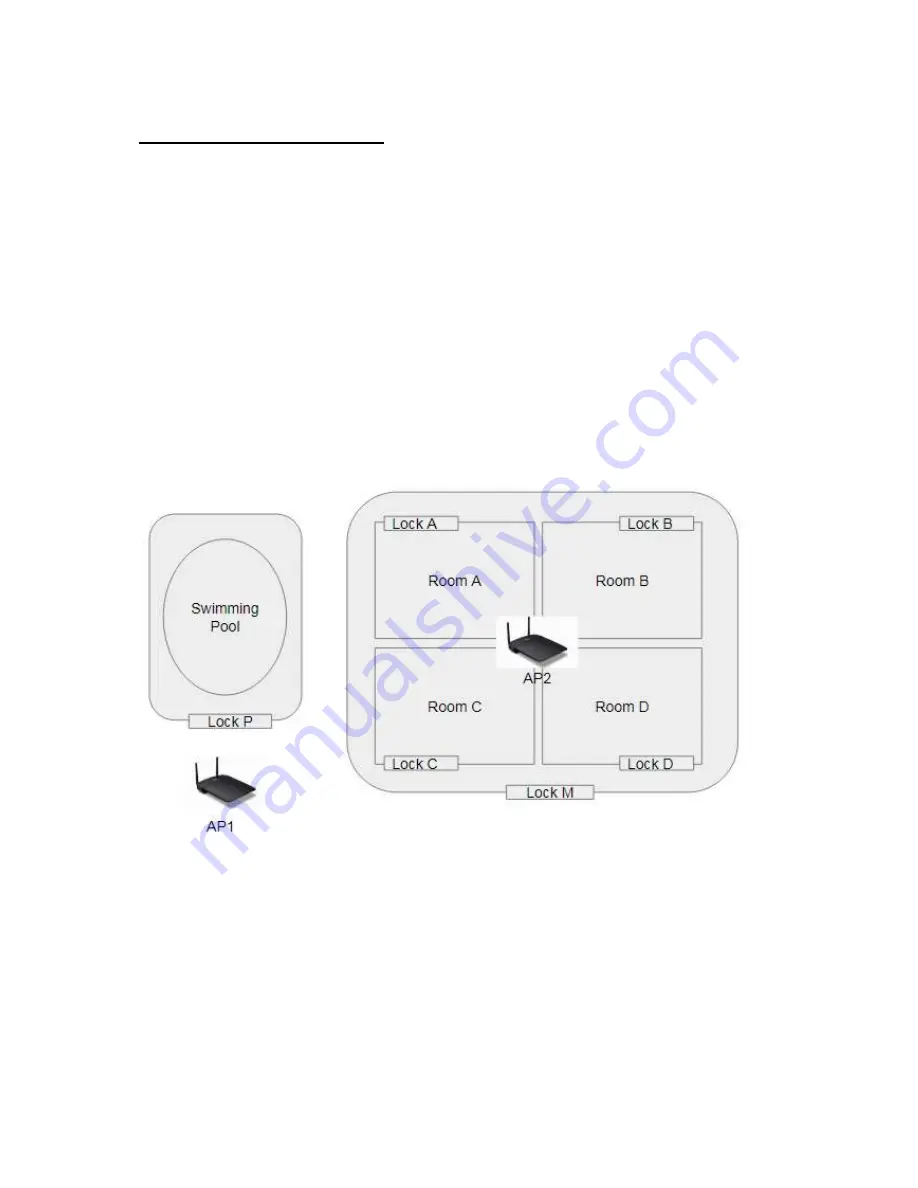
Figure 17: Project SIMPLE
In the SIMPLE project, there are 4 families (A, B, C, D) with one common entrance (M)
and a shared swimming pool controlled by Lock P.
You will have to go through below steps to setup the MF-Admin server and register all
the locks by using alzk account :
Summary of Contents for Kapture KA-WR1S
Page 10: ...9 Front View Figure 3 Kapture KA WR1S Front Kapture KA WR1N Front...
Page 11: ...10 Back View Figure 4 Kapture KA WR1S Back Kapture KA WR1N Back...
Page 13: ...12 Basic Door Installation Figure 6 Kapture KA WR1S N Basic Door Installation...
Page 14: ...13 Basic Door Installation Wiring Figure 7 Kapture KA WR1S N Basic Door Installation Wiring...
Page 15: ...14 Solid State Output Figure 8 Kapture KA WR1S N Solid State Output...
Page 16: ...15 Surface Mounting Figure 9 Kapture KA WR1S N Surface Mounting...
Page 18: ...17 Dimensions Figure 11 Kapture KA WR1S Front Figure 12 Kapture KA WR1N Front...
Page 19: ...18 Back Figure 13 Kapture KA WR1S Back...
Page 20: ...19 Figure 14 Kapture KA WR1N Back...
Page 27: ...26 Product Photo Mark...
Page 28: ...27 Dimensions Mark...
Page 29: ...28 Installation Guide...
Page 32: ...31 Product Photo Mark...
Page 33: ...32 Dimensions Mark...
Page 34: ...33 Installation Guide D1 Installation Guide...
Page 37: ...36 Product Photo Mark...
Page 38: ...37 Dimensions Mark...
Page 39: ...38 Installation Guide...
Page 42: ...41 Product Photo Mark...
Page 43: ...42 Installation Guide...
Page 46: ...45 Product Photo Mark...
Page 47: ...46 Installation Guide...
Page 63: ...62 Place key card on reader first Click Read Key From Reader to get Key s UID...
Page 81: ...80 Place key card on reader first Click Read Key From Reader to get Key s UID...
Page 91: ...90 Check the box on Group Area M and click time control button to edit...
Page 93: ...92 Click Issue Write Key to issue the vendor key Place key card on reader first...
Page 99: ...98 Place key card on reader first Click Read Key From Reader to get Key s UID...
Page 118: ...117 Factory default settings Deadbolt Same as Wall Reader...
Page 119: ...118 Factory default settings Leverset Same as Wall Reader...
Page 120: ...119 Factory default settings Interconnect Same as Wall Reader...
Page 129: ...128 NCC Statement NCC Statement Taiwan Regulatory Information NCC...


