


100
Shutdown Public Area
The only public area we have in SIMPLE project is the swimming pool. Suppose you need to
close the swimming pool in the winter or for maintenance purpose, it is not a good idea to
re-issue all the cards to remove the swimming pool access right.
MF-Admin server has two features: Area Time Control and Lock Scheduling which will help
you to complete this task in a second without re-issuing any cards.
● Area Time Control
Area Time Control is another layer of time control which logically AND with the time
control you set on the Mifare card during card creation for a specific area/lockplace.
Area Time Control setting will take effect to all the residential cards (NOTE:
exceptions exist if you change the access rule, we will discuss it later). Therefore,
when you want to restrict the access of swimming pool to a certain time period of a
day in a weekly manner, area time control is here for this task.
Suppose your card has the access right of swimming pool for 24 hours everyday. And
the area time control of swimming pool is only for Saturday and Sunday 24 hours.
Then you are only able to access swimming pool on Saturday and Sunday.
Note that this approach can not completely shut down the swimming pool because if
you leave all the time control cells blank, it means NO time control. To complete shut
down a public area, you better use Lock Scheduling feature.
To demonstrate how to set the area time control, follow below steps. (Note that you
set time control for an area, not a lock.).
❖
Steps to set area time control for swimming pool
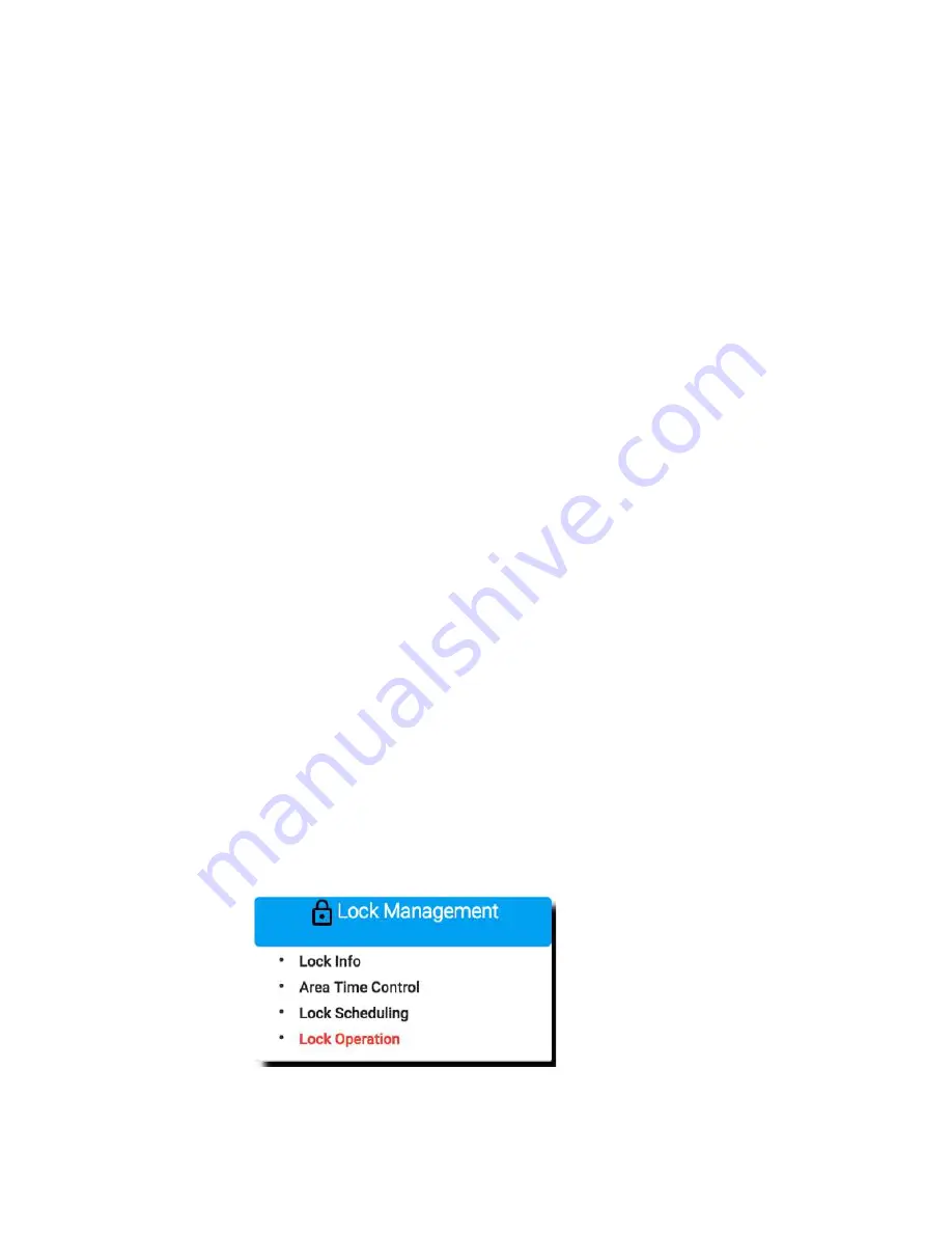
Navigate to Area Time Control Setup page.
Lock Management
=>
Area Time Contro
l
Summary of Contents for Kapture KA-WR1S
Page 10: ...9 Front View Figure 3 Kapture KA WR1S Front Kapture KA WR1N Front...
Page 11: ...10 Back View Figure 4 Kapture KA WR1S Back Kapture KA WR1N Back...
Page 13: ...12 Basic Door Installation Figure 6 Kapture KA WR1S N Basic Door Installation...
Page 14: ...13 Basic Door Installation Wiring Figure 7 Kapture KA WR1S N Basic Door Installation Wiring...
Page 15: ...14 Solid State Output Figure 8 Kapture KA WR1S N Solid State Output...
Page 16: ...15 Surface Mounting Figure 9 Kapture KA WR1S N Surface Mounting...
Page 18: ...17 Dimensions Figure 11 Kapture KA WR1S Front Figure 12 Kapture KA WR1N Front...
Page 19: ...18 Back Figure 13 Kapture KA WR1S Back...
Page 20: ...19 Figure 14 Kapture KA WR1N Back...
Page 27: ...26 Product Photo Mark...
Page 28: ...27 Dimensions Mark...
Page 29: ...28 Installation Guide...
Page 32: ...31 Product Photo Mark...
Page 33: ...32 Dimensions Mark...
Page 34: ...33 Installation Guide D1 Installation Guide...
Page 37: ...36 Product Photo Mark...
Page 38: ...37 Dimensions Mark...
Page 39: ...38 Installation Guide...
Page 42: ...41 Product Photo Mark...
Page 43: ...42 Installation Guide...
Page 46: ...45 Product Photo Mark...
Page 47: ...46 Installation Guide...
Page 63: ...62 Place key card on reader first Click Read Key From Reader to get Key s UID...
Page 81: ...80 Place key card on reader first Click Read Key From Reader to get Key s UID...
Page 91: ...90 Check the box on Group Area M and click time control button to edit...
Page 93: ...92 Click Issue Write Key to issue the vendor key Place key card on reader first...
Page 99: ...98 Place key card on reader first Click Read Key From Reader to get Key s UID...
Page 118: ...117 Factory default settings Deadbolt Same as Wall Reader...
Page 119: ...118 Factory default settings Leverset Same as Wall Reader...
Page 120: ...119 Factory default settings Interconnect Same as Wall Reader...
Page 129: ...128 NCC Statement NCC Statement Taiwan Regulatory Information NCC...


