Pamex Kapture KA-WR1S User Manual & Implementation Manual Download Page 23


22 

Kapture  

KA-WR1S 

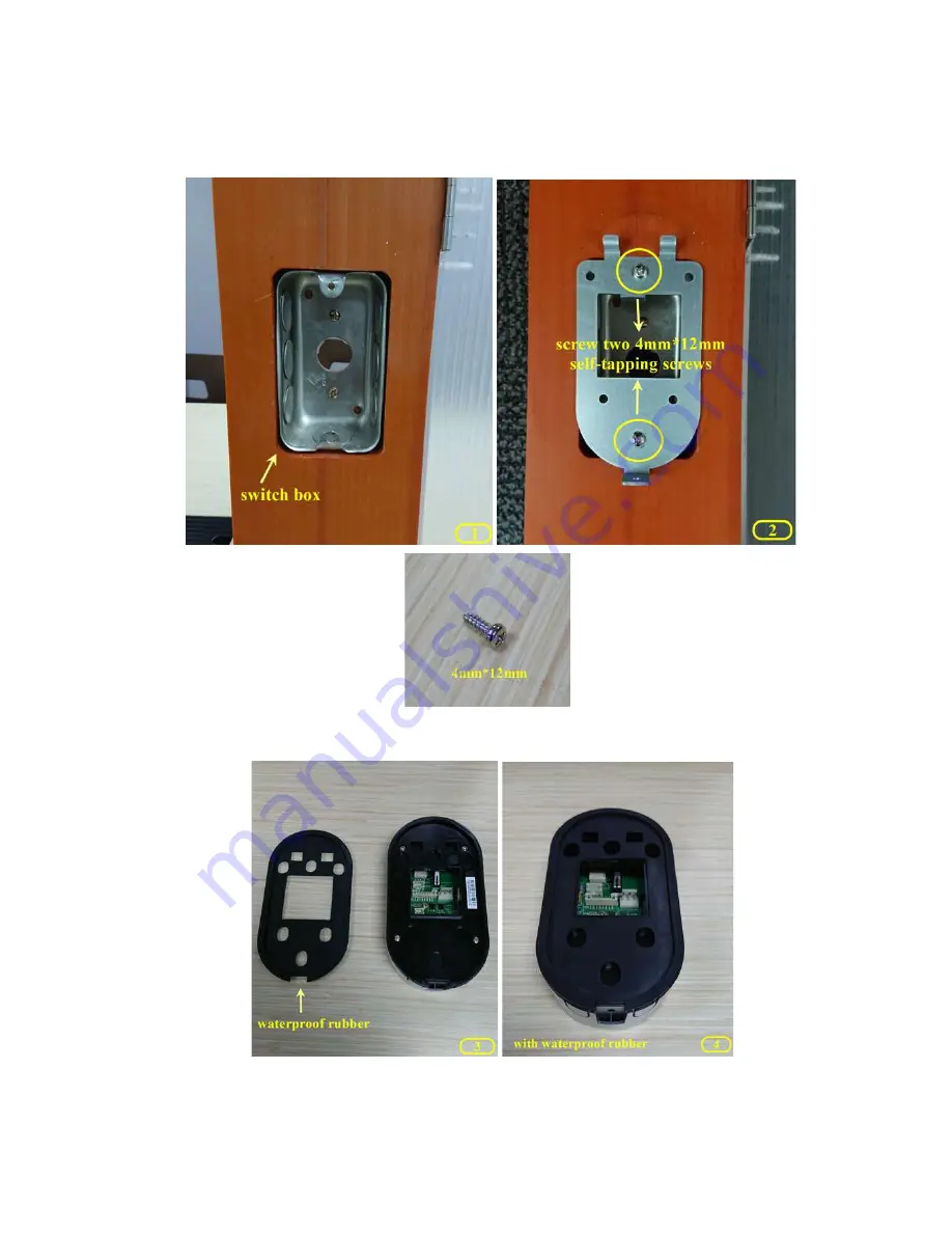
1)  Screw the back plate to switch box with two 4mm*12mm self-tapping screws. See 

picture 1&2. 


2)  Place the waterproof rubber on the back of the Wall Reader. See picture 3&4. 


3)  Before fastened Wall Reader, please ensure the waterproof rubber is installed. 

Align with the hook on the top of back plate. See picture 5. 

Summary of Contents for Kapture KA-WR1S

Page 1: ...Pamex Kapture Series A Multi Family Door Access Control Solution User Manual Implementation Guide...

Page 2: ...3 Solid State Output 14 Surface Mounting 15 Mounting to single gang recessed outlet box 16 Dimensions 17 Installation Guide 20 Deadbolt KA D7P1A Auto 24 Features 24 Hardware Specifications 24 Product...

Page 3: ...tion using Master Card 61 Go live Phase 66 Create Tenant Cards 76 Create Staff Card 83 Create Vendor Card 88 Create Guest Temp Card 95 Shutdown Public Area 100 Area Time Control 100 Lock Scheduling 10...

Page 4: ...plication Parameters 120 System Parameters 120 Mifare Card Specification 121 Card Types 122 Area Types 123 Lock Real Time Events 125 Default Severity of Alert Types 126 FCC Statement 127 NCC Statement...

Page 5: ...e windows server 5 as the client PC 2 MF Admin Server An application running on Windows server 5 It provide all the functions to manage the access control of the locks and the cards fobs 3 Wifi AP All...

Page 6: ...program Please reference MF Admin MP100 installation guide 8 MFSP platform MFSP Multi Family Service Platform is a cloud service for all the MF Admin Servers around the world This platform is operate...

Page 7: ...vice Platform This section is for Pamex only Before any Kapture installation Pamex admin will have to create a project in MFSP in order to get the unique project code A Kapture installation will need...

Page 8: ...rs Passage mode temporarily allow unrestricted access Privacy mode temporarily disable all user access Lockout functionality Dual LED Status Indicators for Visual communications Bi color LED Status In...

Page 9: ...ps 28 Volts max Auxiliary Relay Form C 2 Amp 28 Volts max Electrical life Min 100 000 operations at 2A resister load Electrical life Min 1 000 000 operations at 1A electrical lock Solid state outputs...

Page 10: ...9 Front View Figure 3 Kapture KA WR1S Front Kapture KA WR1N Front...

Page 11: ...10 Back View Figure 4 Kapture KA WR1S Back Kapture KA WR1N Back...

Page 12: ...11 Wiring Pigtail Rated note Figure 5 Kapture KA WR1S Kapture KA WR1N Wiring Pigtail Rated note...

Page 13: ...12 Basic Door Installation Figure 6 Kapture KA WR1S N Basic Door Installation...

Page 14: ...13 Basic Door Installation Wiring Figure 7 Kapture KA WR1S N Basic Door Installation Wiring...

Page 15: ...14 Solid State Output Figure 8 Kapture KA WR1S N Solid State Output...

Page 16: ...15 Surface Mounting Figure 9 Kapture KA WR1S N Surface Mounting...

Page 17: ...16 Mounting to single gang recessed outlet box Figure 10 Kapture KA WR1S N MOUNTING TO SINGLE GANG RECESSED OUTLET BOX...

Page 18: ...17 Dimensions Figure 11 Kapture KA WR1S Front Figure 12 Kapture KA WR1N Front...

Page 19: ...18 Back Figure 13 Kapture KA WR1S Back...

Page 20: ...19 Figure 14 Kapture KA WR1N Back...

Page 21: ...nstallation Guide Kapture KA WR1N 1 Screw the back plate to lock base with three 4mm 12mm self tapping screws See picture below 2 Place the waterproof rubber on the back of the Wall Reader See picture...

Page 22: ...Reader please ensure the waterproof rubber is installed Align the hole with the hook on the top of back plate See picture 3 Push down the Wall Reader See picture 4 Tighten up the Wall Reader with a 4m...

Page 23: ...wo 4mm 12mm self tapping screws See picture 1 2 2 Place the waterproof rubber on the back of the Wall Reader See picture 3 4 3 Before fastened Wall Reader please ensure the waterproof rubber is instal...

Page 24: ...23 Pull down the Wall Reader See picture 6 Tiighten up the Wall Reader with one 4mm 8mm screw See picture 7...

Page 25: ...emporarily allow unrestricted access Privacy mode temporarily disable all user access Lockout functionality Dual LED Status Indicators for Visual communications Bi color LED Status Indicator red green...

Page 26: ...der 5 pin KW keyway standard other options available Door Thickness 1 3 8 35 mm to 2 51 mm Bore 2 1 8 54 mm or 1 1 2 38 mm Backset Adjustable backset fits 2 3 8 60 mm and 2 3 4 70 mm backsets Finish T...

Page 27: ...26 Product Photo Mark...

Page 28: ...27 Dimensions Mark...

Page 29: ...28 Installation Guide...

Page 30: ...tion Access time control for both areas and users Passage mode temporarily allow unrestricted access Privacy mode temporarily disable all user access Lockout functionality Dual LED Status Indicators f...

Page 31: ...Corner Faceplate 1 1 8 x 2 1 4 Cylinder 5 pin KW keyway standard other options available Door Thickness 1 3 8 35 mm to 2 51 mm Bore 2 1 8 54 mm or 1 1 2 38 mm Backset Adjustable backset fits 2 3 8 60...

Page 32: ...31 Product Photo Mark...

Page 33: ...32 Dimensions Mark...

Page 34: ...33 Installation Guide D1 Installation Guide...

Page 35: ...vity logs memory capacity Alert email notification Access time control for both areas and users Passage mode temporarily allow unrestricted access Privacy mode temporarily disable all user access Lock...

Page 36: ...body 75 x 204 x 30 mm Square Corner Lever T strike 1 1 8 x 2 3 4 Cylinder 5 pin KW keyway standard other options available Door Thickness 1 3 8 35 mm to 2 51 mm Bore 2 1 8 54 mm or 1 1 2 38 mm Backset...

Page 37: ...36 Product Photo Mark...

Page 38: ...37 Dimensions Mark...

Page 39: ...38 Installation Guide...

Page 40: ...temporarily allow unrestricted access Privacy mode temporarily disable all user access Lockout functionality Dual LED Status Indicators for Visual communications Bi color LED Status Indicator red gree...

Page 41: ...der 5 pin KW keyway standard other options available Door Thickness 1 3 8 35 mm to 2 51 mm Bore 2 1 8 54 mm or 1 1 2 38 mm Backset Adjustable backset fits 2 3 8 60 mm and 2 3 4 70 mm backsets Finish T...

Page 42: ...41 Product Photo Mark...

Page 43: ...42 Installation Guide...

Page 44: ...ion Access time control for both areas and users Passage mode temporarily allow unrestricted access Privacy mode temporarily disable all user access Lockout functionality Dual LED Status Indicators fo...

Page 45: ...Corner Faceplate 1 1 8 x 2 1 4 Cylinder 5 pin KW keyway standard other options available Door Thickness 1 3 8 35 mm to 2 51 mm Bore 2 1 8 54 mm or 1 1 2 38 mm Backset Adjustable backset fits 2 3 8 60...

Page 46: ...45 Product Photo Mark...

Page 47: ...46 Installation Guide...

Page 48: ...o to lock registration phase then go live phase Each phase requires different tasks to be completed as described below In this guide we will use the term Card or Key from time to time Both term refers...

Page 49: ...at this moment A Construction Card can unlock any locks which has been scanned by Crypto Card given by Pamex for your project only Depending on the lock model lock will present below response when sca...

Page 50: ...s who need to access MF Admin Please check MF Admin Server User Guide to see how to create users The default admin user alzk can not be removed Change the password of alzk immediately is recommended t...

Page 51: ...Area Types for detail An area may contain zero or several lock places which will linked to the physical lock one by one when registering For the SIMPLE project you should prepare a table as below Roo...

Page 52: ...ea tree page Property Management Build Property For a brand new property you will see only one node at beginning Click and edit root area name Click edit button on Root Area and select Add Public Area...

Page 53: ...u button on Root Area and select Add Group Click name text to edit group name Click menu button on Group Area M and select Add Lock Place Edit lockplace name Click menu button on Group Area M and sele...

Page 54: ...k Save To Server to save the area tree Note that there are many ways to build an area tree as above You may find other techniques in MF Admin Server User Manual If you make any mistakes during buildin...

Page 55: ...r ip has to be changed then you have to make new programming cards and all the locks have to be programmed again Some Wifi AP SSID changed For those locks in the range of changed wifi APs you have to...

Page 56: ...r to programm locks in parallel by several workers In the case that several workers are programming locks in parallel please label the UID of the card UID can be found on MF Admin page when you create...

Page 57: ...rds Navigate to system parameters page System Management System Parameters Select Wifi AP Setting Click Add One to add wifi ap and click Save to save wifi ap Navigate to create programming cards page...

Page 58: ...57 You will see there are two wifi aps you added previously Check the checkbox on those wifi ap and click Issue Key Place key card on reader first...

Page 59: ...From Reader to get Key s UID The green light LED on Read should blink If Read Key From Reader failed with three beep sounds and display following message please re place key card and click Read Key F...

Page 60: ...ounds Register Locks to MF Admin Server Please bring a tablet or mobile phone with Chrome browser Follow below steps to register a lock A Open Chrome and type in MF Admin server URL B Login to MF Admi...

Page 61: ...Unit Area A A pop up window will show up listing all the locks not linked yet Click the one you like to link G Link the lock to Room A lockplace G 1 If you link to the wrong lockplace Unlink and link...

Page 62: ...d to MF Admin server they now only recognize Residential Cards plus Master Cards To verify that all the locks are successfully registered and linked to the right lock places in the area tree let s fir...

Page 63: ...62 Place key card on reader first Click Read Key From Reader to get Key s UID...

Page 64: ...ad should blink If Read Key From Reader failed with three beep sounds and display following message please re place key card and click Read Key From Reader again If read key successfully click Write K...

Page 65: ...ommunicate with MF Admin server is to scan an invalid card We will use this approach to save us some time Card X will be the invalid Card Go to lockplace A Scan Card X Scan Master Card and the lock sh...

Page 66: ...ink the lock and register link again Then repeat the verification steps If problem still exist please contact your reseller for help Please keep the Master Card safe and secure Congratulations The sys...

Page 67: ...card from its name There are three supporting features to help you create a residential card You may create a card without using these features but leverage these template features will speed up the p...

Page 68: ...meet the requirement and click Save to save time control setting Let s create another template for house cleaning period According to the requirement house cleaning period only allow at 8 00 12 00 Mon...

Page 69: ...Let s create some user templates We just provide basic information for demo purpose User Type Information Tanant A Kevin Huang kevin alzk com tw Tenant B Tony Lin lintungwei gmail com Tenant C Mark C...

Page 70: ...Tenant The table below the input area will list all the tenants created Please repeat the work and create tenant B C and D Steps to create staffs Navigate to create staffs page User Management Staff E...

Page 71: ...input area will list all the staffs created Follow the same process to create staff Ricky Chang Steps to create vendors Navigate to create vendors page User Management Vendor Edit vendor information a...

Page 72: ...list will be displayed at the bottom of this page Key Template Key template probably is the most useful supporting features when issue many keys It is almost the same as issue a key but you may save...

Page 73: ...72 allowed Steps to create the key template Navigate to create key time control template page Key Management Key Template Select Create New Template Edit Template Name and click Create...

Page 74: ...urs allowed Group Area M 24 hours allowed Let s check the box on Public Area P and no need to edit time control because it s 24 hours open by default Click the clock besides the checkbox can edit the...

Page 75: ...ate Check the box on Public Area P and click its time control button According to the requirement Tenants can access Public Area P 6 00 21 00 Group Area M 24 hours allowed Let s edit the Public Area P...

Page 76: ...time control this time because it s 24 hours open by default Click Save to save TENANTS key template Navigate to key template management page Key Management Key Template You can see those key templat...

Page 77: ...00 21 00 Group Area M 24 hours allowed Unit B 24 hours allowed Card C Public Area P 6 00 21 00 Group Area M 24 hours allowed Unit C 24 hours allowed Card D Public Area P 6 00 21 00 Group Area M 24 hou...

Page 78: ...ants you created in user management function Select tenant kevin to issue key Select tenant kevin will automatically bring his information back to the Basic Information tab Select TENANTS key template...

Page 79: ...Kevin can access Public Area P 6 00 21 00 Group Area M 24 hours allowed Unit A 24 hours allowed We had already set up time control of Public Area P and Group Area M via tenant key template so let s c...

Page 80: ...page we can verify the information of tenant key including Basic Information Unit Area time control information Public Area time control information Group area time control information Click Issue Wri...

Page 81: ...80 Place key card on reader first Click Read Key From Reader to get Key s UID...

Page 82: ...ad should blink If Read Key From Reader failed with three beep sounds and display following message please re place key card and click Read Key From Reader again If read key successfully click Write K...

Page 83: ...82 Write Key Card successfully with two beep sounds Repeat the similar process to create Tenant Cards for B C and D...

Page 84: ...time you can practice to choose the staff information from the staff users you created previously Staff S1 Public Area P 24 hours allowed Group Area M 24 hours allowed Staff S2 Public Area P 24 hours...

Page 85: ...automatically attach staff s information Select STAFFS key template and you will see STAFFS time control settings in Area Control page According to the requirement staff Peter can access Public Area P...

Page 86: ...y the information of staff key including Basic Information Unit Area time control information Public Area time control information Group area time control information Click Issue Write Key to issue Pe...

Page 87: ...From Reader to get Key s UID The green light LED on Read should blink If Read Key From Reader failed with three beep sounds and display following message please re place key card and click Read Key F...

Page 88: ...87 If read key successfully click Write Key Card to issue staff key Write Key Card successfully with two beep sounds Repeat the similar process to create S2 Staff Card...

Page 89: ...ace P and Lockplace M with time control template House Cleaning Period Steps to create vendor card Navigate to Issue Key page Key Management Issue Key Select key type as Vendor Click Select Vendor and...

Page 90: ...k time control button to edit According to the requirement Vendors can access at 8 00 12 00 on every Monday Let s use House Cleaning Period time control template we created before on Public Area P the...

Page 91: ...90 Check the box on Group Area M and click time control button to edit...

Page 92: ...on Group Area M then click Save to save time control setting At the Review Issue Key page we can verify the information of vendor key including Basic Information Unit Area time control information Pub...

Page 93: ...92 Click Issue Write Key to issue the vendor key Place key card on reader first...

Page 94: ...From Reader to get Key s UID The green light LED on Read should blink If Read Key From Reader failed with three beep sounds and display following message please re place key card and click Read Key F...

Page 95: ...94 If read key successfully click Write Key Card to issue vendor key Write Key Card successfully with two beep sounds...

Page 96: ...e used to further restrict access to lockplace to only one time for all the lockplaces granted Below is a demo to create a Guest Card Create a temp card is the same You will request the visitor to ret...

Page 97: ...At Area Control page Check the box on Public Area P and click edit time control button Let s assume guest August can access Public Area P on this weekend edit time control settings and click Save to...

Page 98: ...ge we can verify the information of guest key including Basic Information Unit Area time control information Public Area time control information Group area time control information Click Issue Write...

Page 99: ...98 Place key card on reader first Click Read Key From Reader to get Key s UID...

Page 100: ...Key From Reader failed with three beep sounds and display following message please re place key card and click Read Key From Reader again If read key successfully click Write Key Card to issue guest k...

Page 101: ...u change the access rule we will discuss it later Therefore when you want to restrict the access of swimming pool to a certain time period of a day in a weekly manner area time control is here for thi...

Page 102: ...for Saturday and Sunday 24 hours Let s edit swimming pool time control to meet the requirement click Save to save time control setting You can see the lock on Public Area P turn to light green color w...

Page 103: ...ault Scan card is needed Passage Keep the lock unlocked scan card is not necessary Private It acts like normal mode In combination with the NoPrivacy access rule only Staff Card and Master Card of cou...

Page 104: ...103 Click the lock icon in Public Area P In Operation Mode dialog select Private and click Save The Public Area P lock icon color will turn to light green which means it is not normal setting...

Page 105: ...trol table which you can set when operation mode is in normal mode It is used to manage a public group area where you like it to be passage mode for some period of time of a day in a weekly manner We...

Page 106: ...take card key setting into consideration and ignore the area time control The NoPrivacy rule is a special rule for privacy locks the mode you set at lock scheduling features The card type with NoPriva...

Page 107: ...ing to the document we would want to block all users including the staff to enter swimming pool in private mode Find out the Staff field and edit NoPrivacy to No and click Save Now the swimming pool h...

Page 108: ...he settings for 7 days a week you have another row the bottom row to set time control which is the holiday setting For system to recognize which days are holiday you have use the application parameter...

Page 109: ...holiday Click Save to save the holiday Remove holiday Click X to remove holiday and click Save The holiday setting takes precedence over weekly settings It means if today is holiday and Monday then t...

Page 110: ...ble value might lead to strange system behavior Lock Report Interval Lock report interval can be changed at the Lock Operation function The default value of this parameter is 1800 secs 30 mins for all...

Page 111: ...ate one thing to bare in mind every change to the card or lock will sync to locks in 1800 secs at most For example when you issue a card at 9 00 am the card number will be downloaded to the related ph...

Page 112: ...y semicolon The SMS is not working in current release of MF Admin Server The check intervals are all realtime and can not be modified except the Dead Lock alert Dead Lock alert checking interval can b...

Page 113: ...112 can be controlled by the parameter ALERT_SEVERITY_THRESHOLD parameter in the Misc tab of system parameters function...

Page 114: ...Green LED flash long beep register fail NONE Scan Recovery Card Green LED flash 3 times beep for 3 times Wait for 2 3 secs Online Re Boot Done Scan Residential Card Unlock Green LED flash 1 time beep...

Page 115: ...114 Lock out Red LED flash every 1 sec stop flashing in 1 min default Lock Out Red LED on for 3 minutes default Leverset Deadbolt...

Page 116: ...network setup is out of the scope of this manual Please make sure your network is well configured with your system vendors Pamex Kapture locks support most of the popular wifi APs in the market Pleas...

Page 117: ...ngs Wall Reader Volume 3 high 0 3 Locking Mode 111 scan card enabled touch enabled auto lock enabled Auto Lock Interval 5 secs Report Interval 1800 secs Lockout settings Lockout for 180 secs after 4 f...

Page 118: ...117 Factory default settings Deadbolt Same as Wall Reader...

Page 119: ...118 Factory default settings Leverset Same as Wall Reader...

Page 120: ...119 Factory default settings Interconnect Same as Wall Reader...

Page 121: ...120 MF Admin Server Parameters default settings Application Parameters Please see MF Admin Server User Manual System Parameters Please see MF Admin Server User Manual...

Page 122: ...ctless smart cards and proximity cards The MIFARE brand name covers proprietary solutions based upon various levels of the ISO IEC 14443 Type A 13 56 MHz contactless smart card standard It incorporate...

Page 123: ...the wifi network is ready the only way to unlock the door locks will be using the construction cards Construction cards can not be issued from MF Admin Server It should be provided by Pamex and is un...

Page 124: ...123 Master Card is an unrestricted access card to any door locks in the project It is created using MF Admin server Master Card is only valid to the locks which has registered to MF Admin server...

Page 125: ...the same floor building for example Unit Area An unit area represents an unit for one family Public Area A public area represents a shared facility like swimming pool These areas will be organized int...

Page 126: ...125 Lock Real Time Events 1 Lock Out 2 Cylinder Cover Opened 3 Invalid Key Mifare Desfire Key 4 Single Pass Success...

Page 127: ...rity Locking fail at auto lock disabled mode 30 Unlocking fail at auto lock disabled mode 30 Locking fail at auto lock mode 30 Battery Change 10 Battery Low 100 Firmware upgrade completed 20 Invalid K...

Page 128: ...communications However there is no guarantee that interference will not occur in a particular installation If this equipment does cause harmful interference to radio or television reception which can...

Page 129: ...128 NCC Statement NCC Statement Taiwan Regulatory Information NCC...

Reviews: