


111
prepare an invalid Mifare card (You may issue an invalid card easily by assigning no
area to it). and scan to a lock will serve this purpose.
Alert Settings
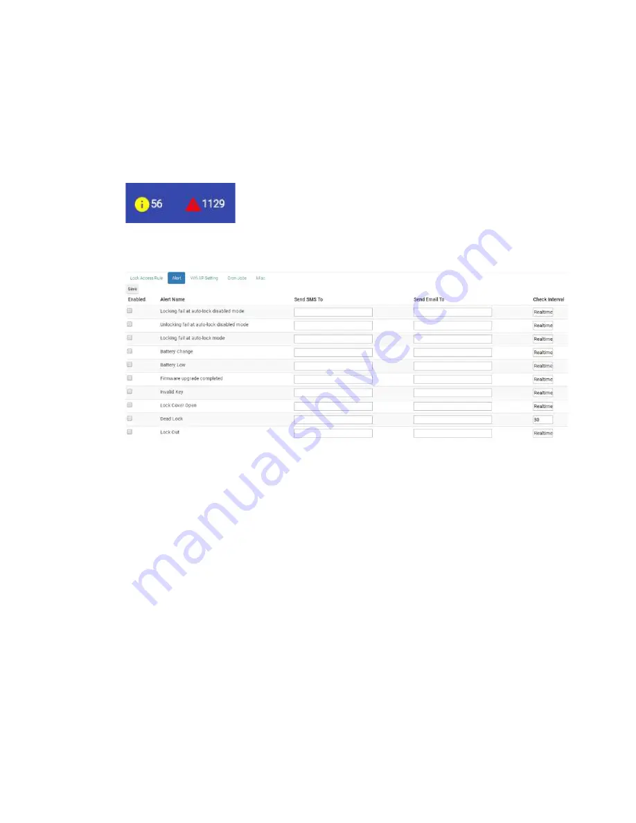
When you login the MF-Admin Server, there are two icons showing the total number of
new alerts at the navigation bar :
In the Alert tab of the system parameters, you can see there are ten types of alert that
will be generated in the system :
There is no alert enabled by default. You may check the checkbox to enable the alerts
you like to see.
You may enter valid email addresses in the “Send Email To” field to enable email
notification for an alert. Multiple addresses can be entered delimited by semicolon.
The SMS is not working in current release of MF-Admin Server.
The check intervals are all realtime and can not be modified except the “Dead Lock”
alert. Dead Lock alert checking interval can be set larger than the default (30 mins).
This value is related to the lock report interval. It is unreasonable to set a dead lock
checking interval smaller than the lock report interval. Note that the unit of this value is
minute.
For every alert types, there is a severity value config in the MF-Admin Server
appConfig.json file. Please read the MF-Admin Server User Manual for how to change
the severity value of each type of alerts. For the default severity setting, please see
Alert Types in the Appendix. An alert will fall into lower severity category (Yellow alerts
on the navigation bar) or higher severity category (Red alerts on the navigation bar)
Summary of Contents for Kapture KA-WR1S
Page 10: ...9 Front View Figure 3 Kapture KA WR1S Front Kapture KA WR1N Front...
Page 11: ...10 Back View Figure 4 Kapture KA WR1S Back Kapture KA WR1N Back...
Page 13: ...12 Basic Door Installation Figure 6 Kapture KA WR1S N Basic Door Installation...
Page 14: ...13 Basic Door Installation Wiring Figure 7 Kapture KA WR1S N Basic Door Installation Wiring...
Page 15: ...14 Solid State Output Figure 8 Kapture KA WR1S N Solid State Output...
Page 16: ...15 Surface Mounting Figure 9 Kapture KA WR1S N Surface Mounting...
Page 18: ...17 Dimensions Figure 11 Kapture KA WR1S Front Figure 12 Kapture KA WR1N Front...
Page 19: ...18 Back Figure 13 Kapture KA WR1S Back...
Page 20: ...19 Figure 14 Kapture KA WR1N Back...
Page 27: ...26 Product Photo Mark...
Page 28: ...27 Dimensions Mark...
Page 29: ...28 Installation Guide...
Page 32: ...31 Product Photo Mark...
Page 33: ...32 Dimensions Mark...
Page 34: ...33 Installation Guide D1 Installation Guide...
Page 37: ...36 Product Photo Mark...
Page 38: ...37 Dimensions Mark...
Page 39: ...38 Installation Guide...
Page 42: ...41 Product Photo Mark...
Page 43: ...42 Installation Guide...
Page 46: ...45 Product Photo Mark...
Page 47: ...46 Installation Guide...
Page 63: ...62 Place key card on reader first Click Read Key From Reader to get Key s UID...
Page 81: ...80 Place key card on reader first Click Read Key From Reader to get Key s UID...
Page 91: ...90 Check the box on Group Area M and click time control button to edit...
Page 93: ...92 Click Issue Write Key to issue the vendor key Place key card on reader first...
Page 99: ...98 Place key card on reader first Click Read Key From Reader to get Key s UID...
Page 118: ...117 Factory default settings Deadbolt Same as Wall Reader...
Page 119: ...118 Factory default settings Leverset Same as Wall Reader...
Page 120: ...119 Factory default settings Interconnect Same as Wall Reader...
Page 129: ...128 NCC Statement NCC Statement Taiwan Regulatory Information NCC...


