MAINTENANCE / REPAIR
TROUBLESHOOTING
OPERATION
ASSEMBLY / INSTALLATION
SAFETY / SPECIFICATIONS
GETTING STARTED
6
ASSEMBLY / INSTALLATION (CONTINUED)
Power source
Running the unit on voltages which are not within the range may
cause over heating and motor burn-out. Heavy loads require that
the voltage at the motor terminals be no less than the voltage
specified.
Electrical connections
Make sure the tool is off before plugging it
into a power source to prevent accidental
starts.
Do not permit fingers to touch the
terminals of plug when installing or
removing from outlet.
Electrical safety
• Double insulated tools are equipped with a polarizing three
pronged plug (one blade is wider than the other.) This plug
will fit in a polarized outlet only one way. If the plug does not
fit fully into the outlet, reverse the plug. If it still does not fit,
contact a qualified electrician to install a polarized outlet. Do
not change the plug in any way.
• Double insulation eliminates the need for the three wire
grounded power cord and grounded power supply system.
Before plugging in the tool, be certain the outlet voltage
supplied is within the voltage marked on the nameplate.
• Avoid body contact with grounded surfaces such as pipes,
radiators, ranges and refrigerators. There is an increased
risk of electric shock if your body is grounded. If operating
the power tool in damp locations is unavoidable, a Ground
Fault Circuit Interrupter must be used to supply the power to
your tool. Rubber soled footwear will further enhance your
personal safety.
4. Don’t expose this or any tools to rain or wet conditions. Water
entering a power tool will increase the risk of electric shock
5. Do not abuse the cord. Never use the cord to carry the tool
or pull the plug from an outlet. Keep cord away from heat,
oil, sharp edges or moving parts. Replace damaged cords
immediately. Damaged cords increase the risk of electric
shock.
Extension cords
• The use of an extension cord will cause some drop in voltage
and loss of power.
• Wires of the extension cord must be of sufficient size to carry
the current and maintain adequate voltage.
• Use the table to determine the minimum wire size (A.W.G)
extension cord.
• Use only 3-wire extension cords having 3-prong grounding
type plugs and 3-pole receptacles which accept the tool plug.
• If the extension cord is worn, cut or damaged in any way,
replace it immediately.
Extension length
Wire Size
A.W.G.
Up to 25 ft
16
25 to 100 ft
14
NOTE: Using extension cords over 100 ft long is not
recommended.
Locating the machine
The Model 9682905 Grinder / Sharpener Machine should
be mounted on a suitable bench or stand. For optimum
performance, it is recommended the supporting device and
machine be leveled.
• Make certain any supporting stands or benches can hold the
machine since it weighs over 100 lbs. It is recommended the
machine be moved with a suitable hoist, forklift or carefully
lifted by two people. Do not stand under the machine while it
is being lifted or suspended.
• Locate the machine where it is easy to remove the power
plug and is easily accessible for maintenance.
Inserting the tool carrier shaft tension knob
1. Locate the Tool Carrier Shaft Tension Knob from the supplied
items.
2. Insert the knob into the hole on the lower left front portion of
the tool and slightly tighten it.
3. The knob acts as a stop and limits the rotation of the tool
carrier shaft under tension.
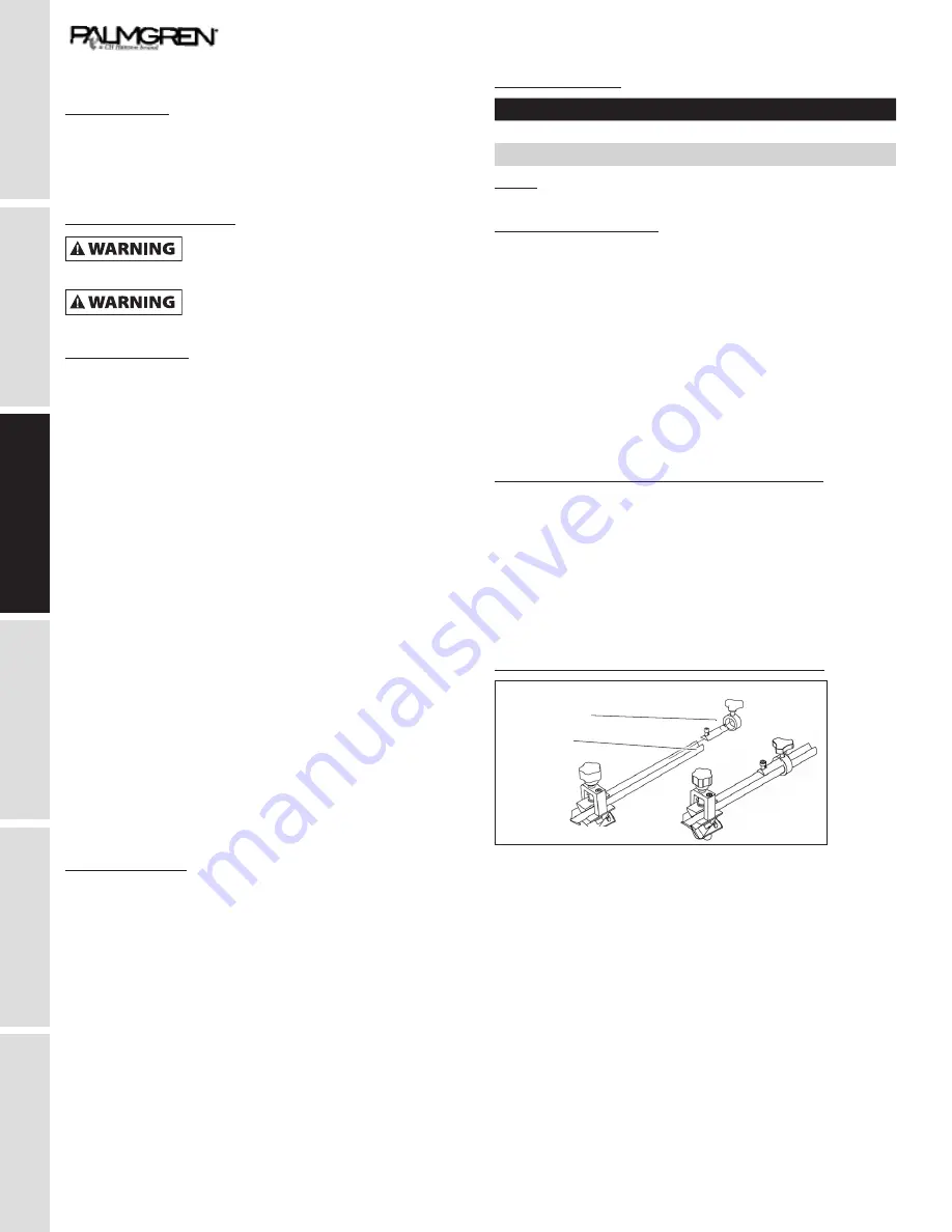
Assembling the drill bit clamping accessory
12
Clamping ring
Clamping
ece
Clamping Ring
Clamping
Piece
The Model 9682905 Grinding / Sharpener can sharpen v-blade
mill bits (burins), end mills, twist drill bits and lathe cutters with
the use of accessories that attach to the Grinder / Sharpener
machine. The Drill Bit Grinding Accessory requires minor
assembly before use.
1. Insert the clamping ring end into the Drill Bit Grinding
Accessory.
2 Tighten the small thumb screw to hold the ring into the
accessory.