ILSL 33/44 Owner‘s Manual
Rev.1.1
37
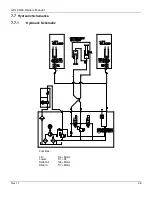
Functional Description of Hydraulics Schematic
7.7.2
Slide Out Function
•
As soon as the Motor starts to run, valve S8 is energized.
•
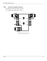
Oil pressure exits pump and motor under pressure to A + B ports on push pull cylinder.
•
The surface at the end of the piston rod on input “B” is larger than on the shaft at input “A”.
•
This creates a stronger force at the piston rod (“B”) than at the shaft (“A”).
•
This factor forces the cylinder to extend.
•
The lift gate will slide out to the end of the rails.
7.7.3
Lower Down
•
The solenoid release valves S1 and S2 at the cylinders get energized.
•
The gate is designed to lower down by gravity. It will push the hydraulic oil out of the lift cylinder
into the reservoir. The oil passes the solenoid release valves S1 and S2.
7.7.4
Lift Up Function
•
Motor starts running oil pressure exits pump and motor to the release valves S1 and S2 are forces
the fulid to push the lift cylinders to extend. The platform raises up.
7.7.5
Slide In Function
•
Motor starts running and S7 valve is energized.
•
The Oil pressure exits pump and motor under pressure to input “A” at the cylinder.
•
The energized valve S7 is allowing the oil at the bottom of the piston rod to get back through the
S5 into the reservoir.
•
The pressure on the end of the shaft will force the piston rod to retract. The liftgate will slide in
under the body.

