


35
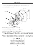
ASSEMBLY
1.
Place the brake housing on a clean, flat surface with
the motor end, or large end, facing up.
2.
Install a brake spacer (Item 305) into the bottom of the
splined bore.
3. Lubricate the friction discs in clean oil, using the same
oil as that intended for the winch gear cavity. Install a
steel brake disk (306) on top of the brake plate spac-
er. Next, install a friction disc (307). Then alternate
steel and friction discs until the last steel disc is placed
on top – nine steel discs and eight friction discs total.
4.
Install the second brake plate spacer (305) on top of
the last steel brake disc. Install the retaining ring (304)
into the groove above the spacer. Make certain the
retaining ring is fully seated into the groove.
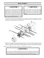
5. Turn the brake housing over and rest it on the motor
end. Make certain the brake plates and spacers are
resting flat on the bottom of the bore and are not hung
up or held out of position. Insert the overrunning brake
clutch assembly to more closely align the splines of
the friction discs. Either support the brake clutch as-
sembly in position with a spacer on the table or re-
move it completely.
BRAKE ASSEMBLY SERVICE
6.
Lubricate the O-rings and backup rings (309, 310, 311,
312) with light grease or petroleum jelly. Install O-rings
and backup rings into the piston grooves. Be sure to
install the backup rings to the outside of the O-rings
toward the ends of the piston. Ensure the concave
surface of the backup rings is against the O-rings.
7.
Install the piston (308) into the brake housing bore. Ap
-
ply light, even pressure to the piston to seat it against
the brake plate spacer.
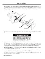
8.
Insert the spring spacer (314) into piston bore. Insert
16 brake springs (313) into the spring pockets created
by the spacer. Two openings will remain in the spacer.
Ensure that openings are located 180 degrees apart.
9.
Install the spring retainer (315) on top of the brake
springs. Using a press, apply even pressure to the re-
tainer to force it just below the bottom face of the re-
taining ring groove and install the retaining ring (316).
Ensure retaining ring is fully seated in the groove be-
fore removing the pressure from the retainer.
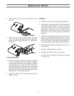
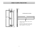
BRAKE ASSEMBLY PRESSURE TEST
Install the long tube fitting into the brake release port of
the brake housing. Connect a hand pump with an accurate
gauge 0–2,000 PSI (0–137.9 bar) and a shut-off valve to
the fitting. Apply 1,000 PSI (68.9 bar) to the brake. Close
the shut-off valve and let the unit stand for 3 to 5 minutes.
If there is any pressure loss, the brake assembly should
be disassembled for inspection of the sealing surfaces
and brake piston seals, and repaired as needed. Perform
this test after any repair to brake assembly.
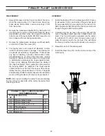
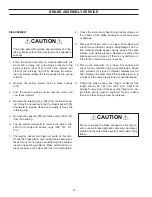
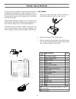
ITEM
NO.
DESCRIPTION
QTY.
301
Brake housing
1
302
Ball, steel
1
303
Pipe plug
1
304
Ring, internal retaining
1
305
Brake plate spacer
2
306
Brake disc
9
307
Friction disc
8
308
Brake piston
1
309
O-ring
1
310
Backup, O-ring
1
311
O-ring
1
312
Backup ring
1
313
Spring
16
314
Spring spacer
1
315
Spring retainer
1
316
Retaining ring
1
306
305
304
303
301
308
314
313
312 311
310
309
315
316
302
307
The brake housing weighs approximately 110 lbs. (50
kg). Ensure lifting equipment has adequate capacity.
CAUTION
!
!


