


OPERATION
11
•
Screw the outer flange (10) onto the spindle with the protruding ring section
facing the angle grinder. This ring section must locate with the hole in the
grinding disc (6).
•
Tighten the outer flange (10) by locking the spindle (using the spindle lock
button) and then tightening the outer flange (10) with the pin spanner (8) provided.
•
Removal of the disc is conducted in reverse order to the above.
•
Regularly check that the outer flange has not loosened during use.
Note:
When fitting a cutting disc or diamond wheel, the ring section on the outer
flange should face away from the disc / wheel in order for the face of the outer
flange (10) to sit flush against the bottom side of the disc / wheel.
Note:
Disc/wheel label or marking, should face towards inner flange.
On/off switch
The angle grinder is started by pushing the lock-on slide switch (3) forward towards
the alloy gear case (1). The lock-on slide switch (3) will lock-on in the ON position.
To turn the angle grinder OFF, push down on the 'O' marking on the rear of the
lock-on slide switch (3). This will cause the switch to retract to the OFF position.
Safety guard
The safety guard (5) is assembled to your tool for your protection. The safety
guard (5) will protect you from any dislodging objects or materials that may be
ejected by the cutting/grinding discs during normal operation. This guard (5) will
protect you from any accidental contact of the disc with your hands, fingers and
any other parts of your body.
To adjust the safety guard (5), first disconnect the tool from the power supply. Now
loosen the allen key bolt (7) by using the allen key (9) supplied. Rotate the safety
guard (5) into the required position, then refasten the bolt (7). Ensure the safety
guard (5) is firmly secured prior to use.
Basic abrasive cutting procedure
First ensure the work piece is securely held down (by both sides of the work piece
if possible). Turn on the angle grinder and proceed to start the cut gently - do not
“bump” the cutting disc to start a cut. Feed the disc through the work as fast as
possible without slowing the cutting disc in the cut or labouring the machine. The
abrasive cutting operation generates a great deal of localised heat which causes
rapid expansion of the piece being cut. Discs operated at speeds significantly
below the efficient speed or if fed through the cut too slowly will generate
excessive heat. Such heat can cause rapid disc wear, fraying around the edge of
the reinforced discs and disc breakage.
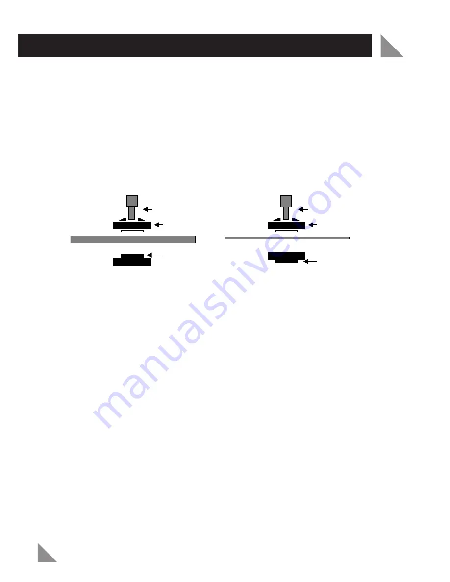
Cutting discs & diamond wheels
Inner flange
Spindle
Outer flange
(raised ring faces AWAY
from the disc/wheel)
Grinding discs
Inner flange
Spindle
Outer flange (raised ring faces
TOWARDS and locates in the
grinding disc)
Grinding discs
Cutting discs & diamond wheels


