10
BE SURE TO DISCONNECT THE ANGLE GRINDER FROM THE POWER
SUPPLY BEFORE ATTACHING OR REMOVING A DISC OR ATTACHMENT.
Make sure the grinding or cutting disc is mounted with the label on top (facing
the angle grinder). If you are fitting any other kind of attachment, refer to
attachment fitting instructions. Ozito Industries P/L will not be responsible for
any damage or injury caused due to the incorrect fitting of grinding or cutting
discs or any other kind of attachment. Incorrect attachments can cause the motor
to burn out, generally damage the tool and/or cause injury.
Assembling the side handle
The side handle (4) can be fitted on either the left or the right hand side of your
grinder. Choose the most appropriate position considering user comfort (preferred
hand) and the task at hand.
Attaching and removing the grinding disc
•
Inspect the grinding disc (6) before fitting and during use to ensure it is not
deformed or cracked.
•
Do not fit or use a grinding disc (6) for cutting applications - For cutting, use a
cutting disc and ask your hardware retailer for advice regarding the type of cutting
disc you require for the material you wish to cut. Grinding discs are used for
grinding metal only.
•
The grinding disc (6) is not solid. It is made from grit which is bonded together
with reinforcement and adhesives. It is always possible that a part of the disc can
dislodge and fly away from the tool at high speed. This is why you must wear the
appropriate safety equipment (glasses, gloves and protective clothing) described
herein and follow all safety instructions also described herein.
•
Do not use any kind of attachment (discs or otherwise) that has a diameter greater
than 100mm (4”).
Warning!
Removing the safety guard (5) is a serious safety concern, this action will
also void your warranty.
•
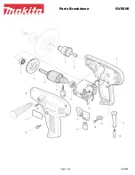
Remove the outer flange (10) by hand if loose. If tight, depress the spindle lock
button (2) at the top of the alloy gear case (1); rotate the spindle (or disc if
attached) to locate the lock position. Once the spindle is locked and cannot be
rotated, use the pin spanner (8) supplied to loosen the outer flange (10).
•
Never press the spindle lock button (2) when the disc or attachment is still rotating.
Always wait until the disc or attachment has stopped rotating before pressing the
spindle lock button (2). Pressing the spindle lock button (2) will cause damage to the
spindlle lock mechanism which will not be covered under warranty.
•
Holding the angle grinder with the spindle facing upwards, ensure the inner flange
(11) is on the spindle and located correctly. The two machined flat sections on one
side of the inner flange (11) must face the angle grinder and locate in the
appropriate position on the spindle.
•
Insert the hole in the grinding disc (6) over the angle grinder spindle with the disc
label facing the angle grinder. The hole in the disc should be located onto the
spindle. Ensure the hole in the disc locates and fits firmly into the ring section of
the inner flange (11).
ASSEMBLY/ADJUSTMENTS