background image

User Manual 

78 


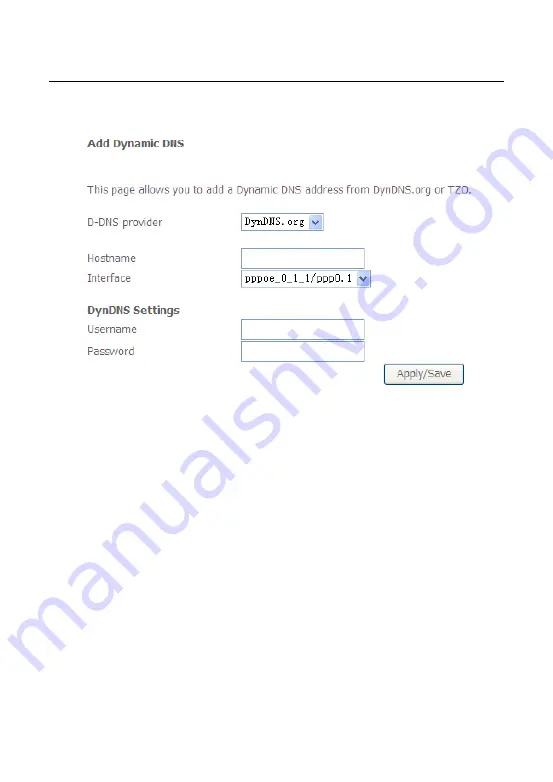
In this page, you are allowed to modify the DDNS settings. 

Click the 

Add

 button to display the following page. 


D-DNS provider: 

Select a proper DDNS server in the drop-down list.


Hostname:

 It is the domain name and it can be modified. 


Interface:

 The interface that the packets pass through on the DSL router. 


Username: 

Enter the username for accessing the DDNS management 

interface. 


Password: 

Enter the password for accessing the DDNS management 

interface.


After finishing setting, click 

Apply/Save

 to save and apply the settings. 

5.2.11  

DSL 

Choose 

Advanced Setup

 > 

DSL

 and the following page appears. In this page, you 

can view the DSL settings. Usually, you can keep this factory default setting.  The 

modem  negotiates  the  modulation  mode  with  the  DSLAM.  If  you  select 

VDSL2 

Enabled

 check box, you can set the VDSL2 parameters on the right area. 

Summary of Contents for OV604WVH

Page 1: ...OV604WVH User Manual VER 1 0...

Page 2: ...he Best Location for Wireless Operation 7 3 2 2 Connecting the Device 8 4 PC Network Configuration and Login 9 4 1 PC Network Configuration 9 4 2 Logging In to the DSL Router 11 5 Web Based Management...

Page 3: ...nterface Grouping 83 5 2 19 IP Tunnel 84 5 2 20 IPSec 86 5 2 21 Certificate 89 5 2 22 Power Management 93 5 2 23 Multicast 94 5 3 Wireless 95 5 3 1 Basic Settings 96 5 3 2 Security 97 5 3 3 MAC Filter...

Page 4: ...24 5 5 2 Fault Management 125 5 6 Management 126 5 6 1 Settings 127 5 6 2 System Log 128 5 6 3 SNMP Agent 129 5 6 4 TR 69 Client 130 5 6 5 Internet Time 130 5 6 6 Access Control 132 5 6 7 Update Softw...

Page 5: ...equirements as prescribed in the appropriate Terminal Equipment Technical Requirements document s This is confirmed by marking the equipment with the Industry Canada certification number The Departmen...

Page 6: ...interface The termination of an interface may consist of any combination of devices subject only to the requirement that the sum of the RENs of all the devices not exceed five L indice d quivalence d...

Page 7: ...it at once Proper space left for heat dissipation is necessary to avoid any damage caused by overheating to the device The holes on the device are designed for heat dissipation to ensure that the devi...

Page 8: ...phone line with standard connectors You can connect the Ethernet interface of WAN to Internet with Ethernet cable for ETH uplink Multiple workstations can be networked and connected to the Internet by...

Page 9: ...s Support RIP v1 RIP v2 WLAN with high speed data transfer rates compatible with IEEE 802 11b g n Optimized Linux 2 6 Operating System IP routing and bridging Asynchronous transfer mode ATM and digita...

Page 10: ...Compatibility and Compliance Support application level gateway ALG ITU G 992 1 G dmt ITU G 992 2 G lite ITU G 994 1 G hs ITU G 992 3 ADSL2 ITU G 992 5 ADSL2 ITU G 993 1 VDSL ITU G993 2 VDSL2 3G WCDMA...

Page 11: ...ftware is upgrading Off The device is powered off Red On The device is initiating Blink The software is upgrading DSL Green On DSL link has established Blink The DSL line is training Off Device is pow...

Page 12: ...WLAN is enabled Blink Data is being transmitted through the wireless interface Off WLAN is disabled WPS Green On Connection succeeds under Wi Fi Protected Setup Blink Negotiation is in progress under...

Page 13: ...then the wireless router starts to accept the negotiation of PBC mode Precautions Do not press the Reset button unless you want to clear the current settings The Reset button is in a small circular h...

Page 14: ...f the splitter through a cable and connect the incoming line to the Line port of the splitter The spliiter has three ports Line Connect to a wall phone jack RJ 11 jack Modem Connect to the Line interf...

Page 15: ...tructed to automatically obtain an IP address using the network DHCP server DSL router provides a DHCP server on its LAN and it is recommended to configure your LAN to automatically obtain its IP addr...

Page 16: ...re as follows Step 1 Choose Start Control Panel Network Connections Step 2 Right click the Ethernet connection icon and choose Properties Step 3 On the General tab select the Internet Protocol TCP IP...

Page 17: ...er do as follows Step 1 Open a Web browser on your computer Step 2 Enter http 192 168 1 1 the default IP address of the DSL router in the address bar The login page appears Step 3 Enter the user name...

Page 18: ...tings and diagnose the system 5 Web Based Management This chapter describes how to use Web based management of the DSL router which allows you to configure and control all of DSL router features and s...

Page 19: ...User Manual 13 5 1 1 Summary Choose Device Info Summary and the following page appears...

Page 20: ...displays the device information such as the board ID software version and the information of your WAN connection such as the upstream rate and the LAN address 5 1 2 WAN Choose Device Info WAN and the...

Page 21: ...ice Info Statistics LAN and the following page appears In this page you can view the statistical information about the recevied and transmitted data packets of the Ethernet and wireless interfaces Cli...

Page 22: ...alues to zero and recount them 5 1 6 xTM Choose Device Info Statistics xTM and the following page appears In this page you can view the statistical information about the recevied and transmitted data...

Page 23: ...User Manual 17...

Page 24: ...to test the xDSL Bit Error Rate Click Reset Statistics to restore the values to zero and recount them xDSL BER Test Click xDSL BER Test to perform a bit error rate BER test on the DSL line The test p...

Page 25: ...BER test completes the following page appears Note If the BER reaches e 5 you cannot access the Internet 5 1 8 Route Choose Device Info Route and the following page appears In this page you can view...

Page 26: ...device connected to the router 5 1 10 DHCP Choose Device Info DHCP and the following page appears In this page you can view the host name the IP address assigned by the DHCP server the MAC address thi...

Page 27: ...User Manual 21 5 2 1 Layer2 Interface 5 2 1 1 ATM Interface Choose Advanced Setup Layer2 Interface ATM Interface In this page you can add or remove to configure DSL ATM Interfaces...

Page 28: ...User Manual 22 Click Add to add ATM Interface and the following page appears...

Page 29: ...for PPPoE IPoE and Bridge PPPoA or IPoA Encapsulation Mode LLC SNAP BRIDGING or VC MUX Service Category UBR Without PCR UBR With PCR CBR Non Realtime VBR Realtime VBR Select Scheduler for Queues of E...

Page 30: ...ce and enter the queue value Click Apply Save to save configuration 5 2 1 3 ETH Interface Choose Advanced Setup Layer2 Interface ETH Interface and the following page appears In this page you can add o...

Page 31: ...ce and the following page appears In this page you are allowed to add remove or edit a WAN service Note If PTM Interface is selected there are three WAN service types PPP over Ethernet PPPoE IP over E...

Page 32: ...click the Add button to display the following page At first you must add a proper ATM or PTM interface for this WAN service Step2 In this page you can select a ATM Interface for the WAN service After...

Page 33: ...User Manual 27 Step3 In this page select the WAN service type to be PPP over Ethernet PPPoE Click Next to display the following page...

Page 34: ...ere all requests from the same internal IP address and port are mapped to the same external IP address and port Furthermore any external host can send a packet to the internal host by sending a packet...

Page 35: ...h PPPoE dial up If this function is enabled the modem uses this IP address as the WAN IP address Enable PPP Debug Mode Enable or disable this function Bridge PPPoE Frames Between WAN and Local Ports E...

Page 36: ...User Manual 30 Step7 In this page you can obtain the DNS server addresses from the selected WAN interface Click Next and the following page appears...

Page 37: ...dding a MER IPoE WAN service This section describes the steps for adding the MER WAN service Step1 In the Wide Area Network WAN Service Setup page click the Add button to display the following page At...

Page 38: ...User Manual 32 Step3 In this page select the WAN service type to be IP over Ethernet enter the service description for this service After finishing setting click Next to display the following page...

Page 39: ...ically or manually enter the IP address provided by your ISP Click Next and the following page appears Note If selecting Obtain an IP address automatically DHCP will be enabled for PVC in MER mode If...

Page 40: ...settings for example enabling NAT enabling firewall and enabling IGMP multicast After finishing setting click Next and the following page appears Step6 In this page select a preferred WAN interface as...

Page 41: ...User Manual 35 Step7 In this page you can obtain the DNS server addresses from the selected WAN interface After finishing setting click Next to display the following page...

Page 42: ...ng a PPPoA WAN service This section describes the steps for adding the PPPoA WAN service Step1 Choose Advanced Setup Layer2 Interface ATM Interface to dsipaly the DSL ATM Interface Configuration page...

Page 43: ...type to be PPPoA and select the encapsulation mode to be VC MUX according to the uplink equipment After finishing setting click the Apply Save button to apply the setings Step3 Choose WAN Service and...

Page 44: ...al 38 Step4 Select the proper interface for the WAN service and then click Next to display the following page Step5 In this page you may modify the service description Click Next to display the follow...

Page 45: ...eout timer If this function is enabled you need to enter the idle timeout time Within the preset minutes if the modem does not detect the flow of the user continuously the modem automatically stops th...

Page 46: ...u want PPPoE mode to support IPTV enable it Step6 In this page you can enter the PPP username and PPP password provided by your ISP Select the authentication method according to your requirement After...

Page 47: ...User Manual 41 Step8 In this page you can obtain the DNS server addresses from the selected WAN interface After finishing setting click Next to display the following page...

Page 48: ...button if necessary 5 2 2 4 Adding an IPoA WAN service This section describes the steps for adding the IPoA WAN service Step1 Choose Advanced Setup Layer2 Interface ATM Interface to dsipaly the DSL AT...

Page 49: ...to be IPoA and select the encapsulation mode to be LLC SNAP ROUTING according to the uplink equipment After finishing setting click the Apply Save button to save the settings Step3 Choose WAN Service...

Page 50: ...al 44 Step4 Select the proper interface for the WAN service and then click Next to display the following page Step5 In this page you may modify the service description Click Next to display the follow...

Page 51: ...this page Network Address Translation NAT allows you to share one Wide Area Network WAN IP address for multiple computers on your Local Area Network LAN If you do not want to enable NAT and wish the u...

Page 52: ...al 46 Step7 After finishing setting click Next to display the following page Step8 In this page select a preferred WAN interface as the system default gateway and then click Next to display the follow...

Page 53: ...ck Apply Save to save and apply the settings You can modify the settings by clicking the Back button if necessary 5 2 2 5 Adding a Bridge WAN service This section describes the steps for adding the Br...

Page 54: ...User Manual 48 Step2 Select the proper ATM Interface and then click Next to display the following page...

Page 55: ...User Manual 49 Step3 In this page you can select the WAN service type and modify the service description for this service After finishing setting click Next to display the following page...

Page 56: ...ears This page is used to configure 3G connection If you want to access the Internet through 3G connection a 3G network card is required Connect the 3G network card to the USB interface of the Router...

Page 57: ...you disable it you need to enter PIN code when using 3G Unlock with PUK PIN If you disable it you need to enter PUK code when failing to enter the PIN code for 3 times Change PIN code Choose it to cha...

Page 58: ...ble the USB modem User Name Username provided by your 3G ISP Password Password provided by your 3G ISP Authentication Method Select a proper authentication method in the drop down list You can select...

Page 59: ...WAN back mechanism The 3G connection is backup for the DSL connection DSL If the DSL is disconnected the 3G starts to dial IP connectivity If the system fails to ping the specified IP address the 3G s...

Page 60: ...form dial up the 3G connection will be disconnected If the DSL WAN connection has established you may manually to perform 3G dial up and then the DSL WAN connection will be disconnected 5 2 4 LAN Conf...

Page 61: ...1 1 Enabling IGMP Snooping IGMP snooping enables the router to forward multicast traffic intelligently instead of flooding all ports in the VLAN With IGMP snooping the router listens to IGMP membersh...

Page 62: ...clients in the LAN Editing the DHCP Option60 Click the Edit DHCP Option60 button in the Local Area Network LAN Setup page to display the DHCP Option60 Setup page In this page you can add edit or dele...

Page 63: ...CP Static IP Lease List The lease list of static IP address can reserve the static IP addresses for the hosts with the specific MAC addresses When a host whose MAC address is in the lease list of stat...

Page 64: ...ce In the Local Area Network LAN Setup page you are allowed to set the second IP address and the subnet mask for a LAN interface After enabling Configure the second IP Address and Subnet Mask for LAN...

Page 65: ...and enable the MLD snooping function Enable DHCPv6 Server WIDE DHCPv6 is an open source implementation of dynamic host configuration protocol for IPv6 DHCPv6 originally developed by the KAME project T...

Page 66: ...ges a Layer 2 device running MLD Snooping establishes mappings between ports and multicast MAC addresses and forwards IPv6 multicast data based on these mappings After finishing setting click the Save...

Page 67: ...o virtual server External Port Start When selecting a service the port number will automatically be displayed You can modify it if necessary External Port End When selecting a service the port number...

Page 68: ...ort Triggering Some applications need some ports to be opened in the firewall for the remote access When an application initializes a TCP UDP to connect to a remote user port triggering dynamically op...

Page 69: ...gger the open port Trigger port End The end port number that LAN uses to trigger the open port Trigger Protocol Select the application protocol You may select TCP UDP TCP or UDP Open Port Start The st...

Page 70: ...firewall Choose Advanced Setup NAT DMZ host to display the following page In this page enter the IP address of the DMZ host After finishing the settings click the Apply Save button to apply the settin...

Page 71: ...ge appears enabled Select the check box to enable the firewall rule Protocol You can select UDP TCP or ICMP from the drop down list Action You can select Permit Drop or Reject from the drop down list...

Page 72: ...k Save Apply to save and activate the rule MAC Filtering Setup In some cases you may want to manage Layer2 MAC address to block or permit a computer within the home network When you enable MAC filter...

Page 73: ...ess Enter the destination MAC address Source MAC Address Enter the source MAC address Frame Direction The direction of transmission frame WAN Interface Configured in bridge mode only Select the proper...

Page 74: ...vanced Setup Parental Control Url Filter and the following page appears Thisp age is used to prevent the LAN users from accessing some Websites in the WAN In this page you may select the Exclude URL l...

Page 75: ...nding port number For example enter the URL address http www google com and the port number 80 and then click the Apply Save button See the following figure 5 2 8 Quality of Service Enabling QoS Choos...

Page 76: ...finishing setting click Apply Save to save and apply the settings Note If the Enable Qos checkbox is not selected all QoS will be disabled for all interfaces The default DSCP mark is used to mark all...

Page 77: ...1 In this page you can enable add or remove a QoS rule Note The lower integer value for precedence indicates the higher priority Click the Add button to display the following page Name Enter the name...

Page 78: ...ueue After finishing setting click Apply Save to save and apply the settings QoS Classification Choose Advanced Setup Quality of Service Qos Classification and the following page appears In this page...

Page 79: ...User Manual 73 5 2 9 Routing Default Gateway Choose Advanced Setup Routing Default Gateway and the following page appears...

Page 80: ...of Selected WAN Interface as the system default gateway After finishing setting click Apply Save to save and apply the settings Static Route Choose Advanced Setup Routing Static Route and the followi...

Page 81: ...r the rule Gateway IP Address The next hop IP address Metric The metric value of routing After finishing setting click Apply Save to save and apply the settings Policy Routing Choose Advanced Setup Ro...

Page 82: ...click Apply Save to save and apply the settings RIP Choose Advanced Setup Routing RIP and the following page appears In this page if you want to configure an individual interface select the desired RI...

Page 83: ...page you can select a DNS server interface from the available interfaces manually enter the DNS server addresses or obtain the DNS address from a WAN interface After finishing setting click Apply Save...

Page 84: ...name Enter the username for accessing the DDNS management interface Password Enter the password for accessing the DDNS management interface After finishing setting click Apply Save to save and apply t...

Page 85: ...can set the DSL settings Usually you do not need to modify the factory default settings After finishing setting click Apply Save to save and apply the settings 5 2 12 UPnP Choose Advanced Setup UPnP...

Page 86: ...Setup DNS Proxy and the following page appears In this page you can enable or disable the DNS proxy function After enabling the DNS proxy function enter the host name of the broadband router and the...

Page 87: ...ing click Apply Save to save and apply the settings 5 2 15 DLNA Choose Advanced Setup DLNA and the following page appears In this page select the Enable on board digital media server check box and the...

Page 88: ...ng page appears In this page you can enable packet flow accelerator 5 2 17 Storage Service Storage Device Info Choose Advanced Setup Storage Service Storage Device Info and the following page appears...

Page 89: ...dging groups Each group will perform as an independent network To support this feature you must create mapping groups with the appropriate LAN and WAN interfaces using the Add button The Remove button...

Page 90: ...onfigure the parameters of the interface grouping After finishing setting click Apply Save to save and apply the settings 5 2 19 IP Tunnel 5 2 19 1 IPv6 in IPv4 Choose Advanced Setup IP Tunnel IPv6inI...

Page 91: ...the following page appears In this page you can add a new tunnel IPv4 Mask Length The value is 0 32 6rd Prefix with Prefix Length prefix length such as 2002 64 After proper settings click Apply Save a...

Page 92: ...oose Advanced Setup IP Tunnel IPv4inIPv6 and the following page appears Click Add and the following page appears In this page you can add a new tunnel of IPv4 in IPv6 5 2 20 IPSec Choose Advanced Setu...

Page 93: ...User Manual 87 In this page you can add or remove the IPSec tunnel connections Click the Add button to display the following page...

Page 94: ...me tunnel mode and remote IPSec gateway address If you need to configure the advanced settings of this IPSec tunnel connection please click the Show Advanced Settings button to display the other param...

Page 95: ...st button to display the following page In this page please set the following parameters Certificate name Set the certificate name Common Name The common name is the fully qualified domain name or FQD...

Page 96: ...on s head office is located Please enter the full name of the state or province Country Region Name This is the two letter ISO abbreviation for your country for example GB for the United Kingdom After...

Page 97: ...aste the signed certificate and then click the Apply button A new certificate is created Importing an Existing Local Certificate To import an existing certificate click the Import Certificate button t...

Page 98: ...nual 92 In this page paste the certificate and the private key Finally click the Apply button to import the certificate Trusted CA Choose Advanced Setup Certificate Trusted CA and the following page a...

Page 99: ...page enter the certificate name and paste the certificate content Finally click the Apply button to import the certificate 5 2 22 Power Management Choose Advanced Setup Power Management and the follow...

Page 100: ...User Manual 94 After proper configurations click Apply to take the configurations effect 5 2 23 Multicast Choose Advanced Setup Multicast and the following page appears...

Page 101: ...l 95 In this page you can configure the multicast parameters After finishing setting click Apply Save to save and apply the settings 5 3 Wireless Choose Wireless and the submenus of Wireless are shown...

Page 102: ...en the clients that connect to the same access point you can select this option Disable WMM Advertise After enabling this option the transmission performance multimedia of the voice and video data can...

Page 103: ...ware version three virtual access points can be configured After finishing setting click Apply Save to save the basic wireless settings and make the settings take effect 5 3 2 Security Choose Wireless...

Page 104: ...AP Push button configuration PBC an actual push button on the hardware or through a simulated push button in the software This is an optional method on wireless client If you are using the PIN method...

Page 105: ...en Mode Select SSID Select a SSID for configuring the security settings Network Authentication Select the Open mode WEP Encryption Enable or disable WEP encryption After enabling this function you can...

Page 106: ...If it is 128 bit key you need to enter 13 ASCII characters or 26 hexadecimal digits For the 64 bit key you need to enter 5 ASCII characters or 10 hexadecimal digits Shared Mode The parameters descript...

Page 107: ...ou can set 64 bit or 128 bit key Current Network Key The current key that you use Network Key1 2 3 4 Set the network key If it is 128 bit key you need to enter 13 ASCII characters or 26 hexadecimal di...

Page 108: ...t a SSID for configuring the security settings Network Authentication Select the WPA PSK mode WPA WAPI passphrase The key for WPA encryption Click the Click here to display button to display the curre...

Page 109: ...ng key RADIUS Server IP Address Enter the IP address of the RADIUS server RADIUS server is used to authenticate the hosts on the wireless network RADIUS Port The port number that the RADIUS server use...

Page 110: ...tion of Mixed WPA2 WPA mode please refer to the WPA2 mode Mixed WPA2 WPA PSK The parameters description of Mixed WPA2 WPA PSK mode please refer to the WPA PSK mode 5 3 3 MAC Filter Choose Wireless MAC...

Page 111: ...ltering function Allow Allow the wireless clients with the MAC addresses in the MAC Address list to access the wireless network of the wireless router Deny Reject the wireless clients with the MAC add...

Page 112: ...Bridge Bridge Restrict Enable or disable the bridge restrict function Remote Bridges MAC Address Enter the remote bridge MAC address After finishing setting click the Apply Save button to save and app...

Page 113: ...imer min Specifies the timer of auto channelling 802 11n EWC Select disable 802 11n or Auto Bandwidth Select the bandwidth for the network You can select 20MHz in 2 4G Band 40MHz in 2 4G Band Control...

Page 114: ...is Auto Basic Rate Select the basic transmission rate ability for the AP Fragmentation Threshold Packets that are larger than this threshold are fragmented into multiple packets Try to increase the f...

Page 115: ...gory is set to Disable meaning that an acknowledge packet is returned for every packet received This provides a more reliable transmission but increases traffic load which decreases performance To dis...

Page 116: ...nus of Voice are shown as below 5 4 1 VoIP Status Choose Voice VoIP Status and the Voice Status page appears In the Registration Status field Up means registered successfully Down means unregistered D...

Page 117: ...User Manual 111 Figure 6 SIP Basic Setting 1...

Page 118: ...ce Name you can select the bound interface name from the drop down list SIP Local Port Set the SIP local port of the gateway the default value is 5060 SIP local port is the SIP UA user agent port SIP...

Page 119: ...network to the Internet When it is selected the following fields appear SIP Outbound Proxy The IP address of the outbound proxy SIP Outbound Proxy port The port that the outbound proxy is listening o...

Page 120: ...but more loads on the network traffic Priority The priority of codec is declined from up to down Codecs define the method of relaying voice data Different codecs have different characteristics such as...

Page 121: ...User Manual 115 Figure 8 SIP Advanced Setting 1...

Page 122: ...figure Call waiting If call waiting is enabled on a line you can hear the call waiting tone during a call press FLASH on the phone to answer the second call The first call is automatically placed on h...

Page 123: ...s function Forward on no answer Select the check box to enable this function MWI When selecting message waiting indicator MWI the DSL router sends a SIP SUBSCRIBE message to the proxy asking for a not...

Page 124: ...freshing time Min Session Expire Time The minimum interval of dialog refreshing time VoIP DialPlan Setting Set the VoIP dial plan If user dialed number matches it the number is processed by the DSL ro...

Page 125: ...ervice can not be set by the telephone set After setting click Apply to take the settings in to effect 5 4 4 SIP Extra Setting Choose Voice SIP Extra Setting and the following page appears Dial tone t...

Page 126: ...ten an amplifier to increase the power or amplitude of a signal You can increase or decrease ingress gain and egress gain The range of the value is from 14 to 6 5 4 6 VoIP Functionality This section d...

Page 127: ...er on the phone 2 Hear the dial tone Dial the extension of remote party 3 To end the dialing wait for digit timeout or just press immediately 4 After the remote party answers the call you are in voice...

Page 128: ...ice connection When another call comes in the DSL router streams a call waiting tone to your phone indicating another call is available 4 Press FLASH to switch to this call and the initial call put to...

Page 129: ...g the forwarding number and enable the feature 1 Set Busy Call forwarding number and enable Forward on busy in the Voice SIP Advanced Setting web page 2 When our phone is busy this call can be forward...

Page 130: ...T38 mode and use it as the transmit approach 5 4 6 15 Pass Through Faxing If T38 support is disabled faxing uses normal voice codec as its coding approach Therefore this mode more like normal phone ca...

Page 131: ...User Manual 125 5 5 2 Fault Management Note The Fault Management is only available for VDSL PTM Click Diagnostics Fault Management and the following page appears...

Page 132: ...User Manual 126 5 6 Management Choose Management and the submenus of Management are shown as below...

Page 133: ...oose Management Settings Update and the following page appears In this page click the Browse button to select the correct new settings file and then click the Update Settings button to update the rout...

Page 134: ...Remote and Both Local When selecting Local the events are recorded in the local memory Remote When selecting Remote the events are sent to the specified IP address and UDP port of the remote system lo...

Page 135: ...ystem log Click the Refresh button to refresh the system log Click the Close button to exit 5 6 3 SNMP Agent Choose Management SNMP Agent and the following page appears Simple Network Management Proto...

Page 136: ...TR 069Client to display the following page WAN Management Protocol TR 069 allows an Auto Configuration Server ACS to perform auto configuration provision collection and diagnostics to this device In t...

Page 137: ...Manual 131 In this page you may configure the router to synchronize its time with the Internet time servers After enabling Automatically synchronize with Internet time servers the following page appe...

Page 138: ...Control Passwords Choose Management Access Control Passwords and the following page appears In the page you can modify the username and password of different users After finishing setting click the A...

Page 139: ...you can enable or disable the different types of services After finishing setting click the Apply Save button to save and apply the settings 5 6 7 Update Software Choose Management Update Software an...

Page 140: ...y reboots Please make sure that the new software for updating is correct and do not use other software to update the router 5 6 8 Reboot Choose Management Reboot and the following page appears In this...

Page 141: ...router A Choose Start Run from the desktop and ping 192 168 1 1 IP address of the DSL router If the DSL router is not reachable check the type of the network cable the connection between the DSL route...

Reviews: