4
a database with a wide range of preset objects. The hand
controller display is backlit for comfortable viewing. Make
sure not to confuse the “HC” jack with the “AUX” jack. The
“AUX” jack is not used for normal operation of the mount.
Note: Do not attempt ot reposition the altitude or azimuth
of the mount by hand! Doing so can damage the gears
and motors within the mount.
3. Powering the teletrack
aZ‑G Mount
The TeleTrack AZ-G mount can be powered by 8 AA batteries,
an optional 12V DC power supply, or an optional AC adapter.
Powering by aa Batteries
For maximum portability, the TeleTrack AZ-G mount features a
battery compartment that holds eight (8) AA alkaline batteries
(user supplied). To open the compartment, press down on the
black battery compartment latch (see Figure 3) and gently lift
the cover off. You will find two separate battery holders that
hold 4 AA batteries each. For easiest installation, detach each
battery holder and insert your AA batteries until each holder
is full. Be sure to orient the batteries as indicated on the bat-
tery holder. Reattach the filled battery holders securely using
the snap connectors and close the battery compartment by
pressing its cover down gently until its latch clicks. Power the
TeleTrack AZ-G on by pressing the red on/off switch to the “on”
position.
Powering by External Power source
Portable Battery
For optimal results, we recommend using a portable recharge-
able battery like the Dynamo Pro available from Orion. These
12V DC batteries will power the mount far longer than stan-
dard AA batteries. Make sure your rechargeable battery is tip
positive and capable of producing continuous current with a
minimum of 1 amp.
If you are using a portable battery like the Orion Dynamo
Pro, use the Dynamo’s supplied 12V DC power cable (ciga-
rette lighter plug on one end, standard 12V DC power plug
on the other end) to connect the battery to the 12V “DC IN”
(Figure 4b) power jack on the side of the mount. Make sure
the Dynamo’s power switch is in the “off” position when con-
necting cables. Power the TeleTrack AZ-G on by pressing the
red on/off switch to the “on” position
AC Adapter
In addition, the mount can be powered by an optional AC
adapter rated at 12V DC, 1000mA, tip positive. Plug the adapt-
er cord into the “DC IN” power jack for operation. Power the
TeleTrack AZ-G on by pressing the red on/off switch to the “on”
position.
Power output
Unlike many mounts in its class, the TeleTrack AZ-G Mount
will provide power output for accessories like digital cameras
or camcorders. It accepts a DC power plug (tip positive) and
provides 12V DC power output. To power a 12V accessory
with the TeleTrack AZ-G, simply plug the accessory’s 12V DC
power cable into the “DC OUT” (Figure 4b) jack on the side of
the mount.
Caution: Never plug an external power supply cord into
the “12V DC OUT” jack accidentally. This may damage the
AA batteries inside the battery compartment, and possi-
bly damage the mount itself.
4. attaching a telescope or
camera
usinG tHE l‑BracKEt
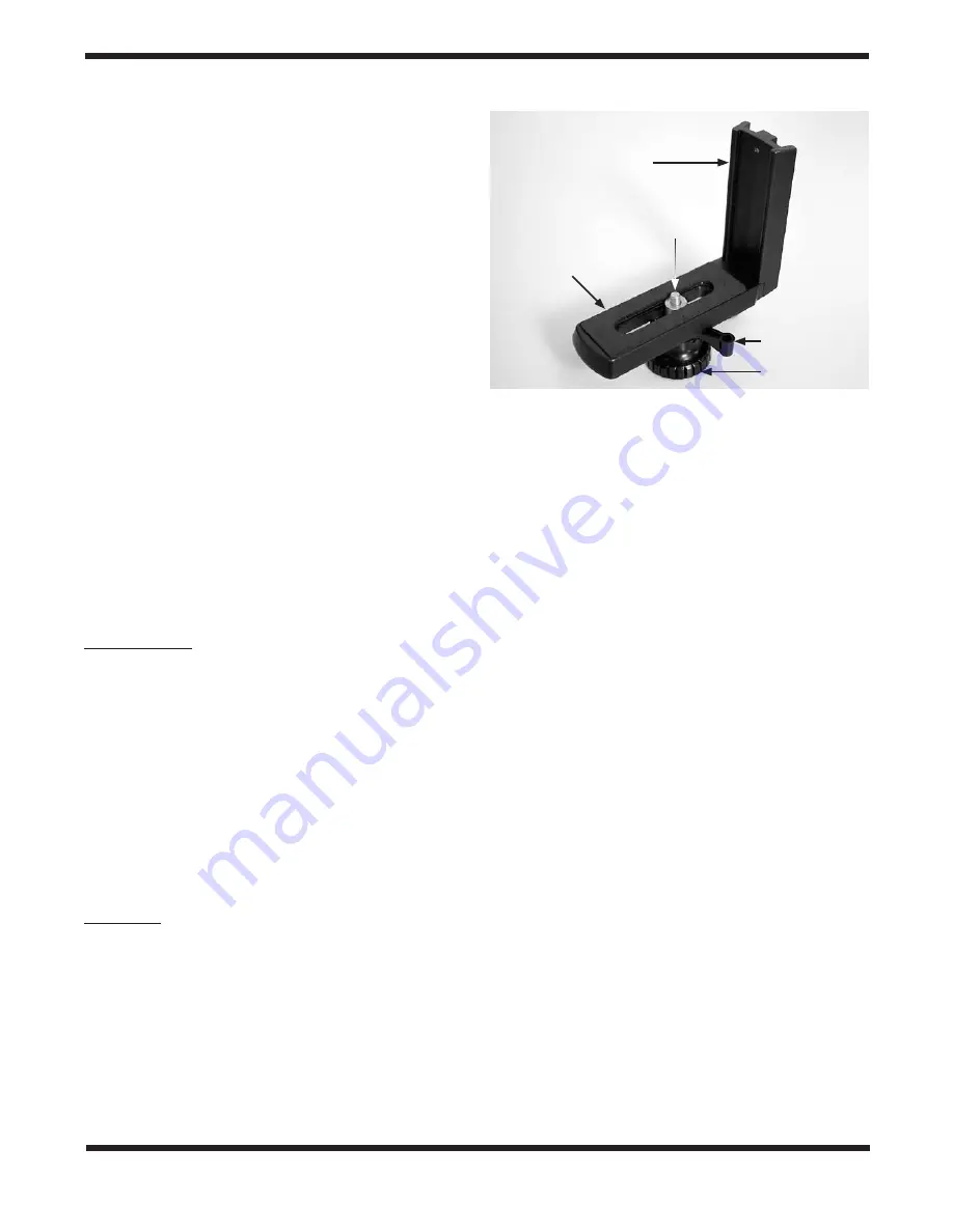
Your TeleTrack AZ-G Mount comes with a convenient L-bracket
(Figure 5) that provides coupling to the mount with the stan-
dard ¼"-20 threaded hole found on most cameras, camcord-
ers, and many telescopes.
attaching an instrument to the l‑bracket
With the foam-padded base of the L-bracket facing upward,
gently place the ¼"-20 threaded hole in your optical instru-
ment onto the ¼"-20 threads on the L-bracket. Turn the black
knurled knob so the ¼"-20 threaded post completely engages
the ¼"-20 threaded hole in your telescope, spotting scope, or
camera. Tighten by rotating the tightening lever on the under-
side of the L-bracket until secure.
attaching the l‑bracket to the Mount
The L-bracket has a short dovetail plate that slides into the
corresponding dovetail mount on the fork arm. The other sec-
tion of the L-bracket has a foam-padded base for your tele-
scope or camera.
Insert the dovetail plate of the L-bracket into the dovetail
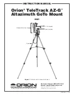
mount, making sure that it is oriented as shown in Figure 3.
Then tighten the dovetail lock knob until snug.
Figure 5:
The TeleTrack AZ-G GoTo Mount ¼"-20 L-bracket
Dovetail
Plate
Tightening
Lever
Knurled Knob
Foam
Padded base
¼"-20
Threaded Post


