


- 78 -
OPM-4250 | OPM-4250R
- 79 -
Infinitely Expandable
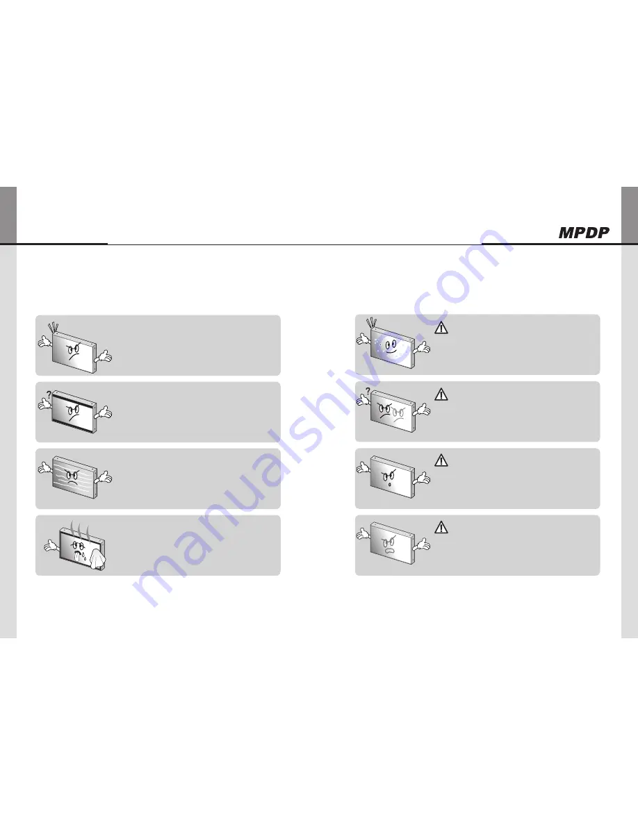
Other tips
7.
▶"Tick" sound from the main body.
Ifthereisnoproblemwiththescreenorsound,the"tick"soundislikelytoresultfrom
y
thecabinetlightlyshrinkingwiththechangeofroomtemperature.Thesounddoes
notaffectproduct’sperformance.
▶no image at upper and lower part of the screen.
Asforascreenwhichisover16:9inwidth(suchascinema-sizedone),noimage
y
maybedisplayedatupperandbottompartofthescreen.
▶Speckles or white lines on the screen
Checkwhethertheproblemiscausedbyvehicle,streetcar,high-voltagecableor
y
neonsign,whichemittinginterferencewaveorelectromagneticinduction.Avoidany
interferingobject.
▶Screen or PDP Set is hot
PDPsetsorscreencanbehot,becausebasicprincipleofPDPdrivingisPlasma
y
dischargebetweenelectrodes.
Itisnotadefectoramalfunctionoftheproduct,youmaycontinuetousetheproduct.
y
Before calling for service
7.1.
Beforecallingforanyrepair,checkthefollowingandthenrefertoanearA/Scenter.
About Plasma display panel
7.2.
Thefollowingsarephenomenacausedbycharacteristicsoftheplasmadisplaypanel.
Sinceitisnotafault,youmaycontinuetousetheproduct.
▶Black or twinkling spots on the screen
Althoughtheplasmadisplaypanelismanufacturedwithhigh-precision
y
technology,theremayexistblackortwinklingspotsonthescreen.
Sinceitisnotafault,youmaycontinuetousetheproduct.
▶Burn-in effect
Displayingstaticimagessuchasstillvideoframesorcomputerscreen
y
imagesforanextendedperiodoftimemaycauseburn-ineffect.
Theburn-ineffectmaybegraduallyreducedbydisplayingfullwhite
pattern.
However,pleasealwaysbecarefulinusingstaticimagesonthisproduct,
y
becausesuchburn-ineffectmaycausepermanentdamagesinsome
cases.
▶noise from the inside
Whenyouturnontheproductslightbuzzingsoundmaybeheard
y
fromtherearofdisplaypanel.Sinceitisnotafault,youmaycontinue
tousetheproduct.
▶Screen decolorization
Opticalfilmthatisattachedonthepanelcanbeslightlydecolorized
y
afterlongtimeofuse.Thedegreeofdecolorizationmayvary
dependingondisplaycontentsandconditions.
Itisduetothecharacteristicsofthefilm,butitisnotadefect.
(Itiscausedbychemicalcharacteristicsofthefilm.)
Caution
Caution
Caution
Caution
Summary of Contents for OPM-4250
Page 45: ...86 OPM 4250 OPM 4250R Memo...


