


- 1 -
Infinitely Expandable
Features of MLCD
▶
Enjoy a wide flat screen with high brightness and high quality.
▶
Easy to install and move due to its thin design
▶
Enjoy your favorite programs with various split-screen features simultaneously presenting
several programs.
To prevent electric shock, Do not remove cover.
No user serviceable part inside
Refer servicing to qualified service personal.
Warning
Thank you for purchasing our MLCD monitor.
This manual describes how to use the product and notes in use.
Please read the manual carefully before using it.
After reading this manual, please retain for future reference.
If you have any questions or a problem occurs, please contact either the company you purchased this
product from or an authorized service center.
※
Displaying static picture for an extended period of time may cause an burn-in effect.
※
Burn-in effect and the faults in brightness and picture elements caused by fixed images are not subject
to the warranty coverage.
If you fail to comply with the regulations for safety and proper use,
fire or injury may be caused.
Warning
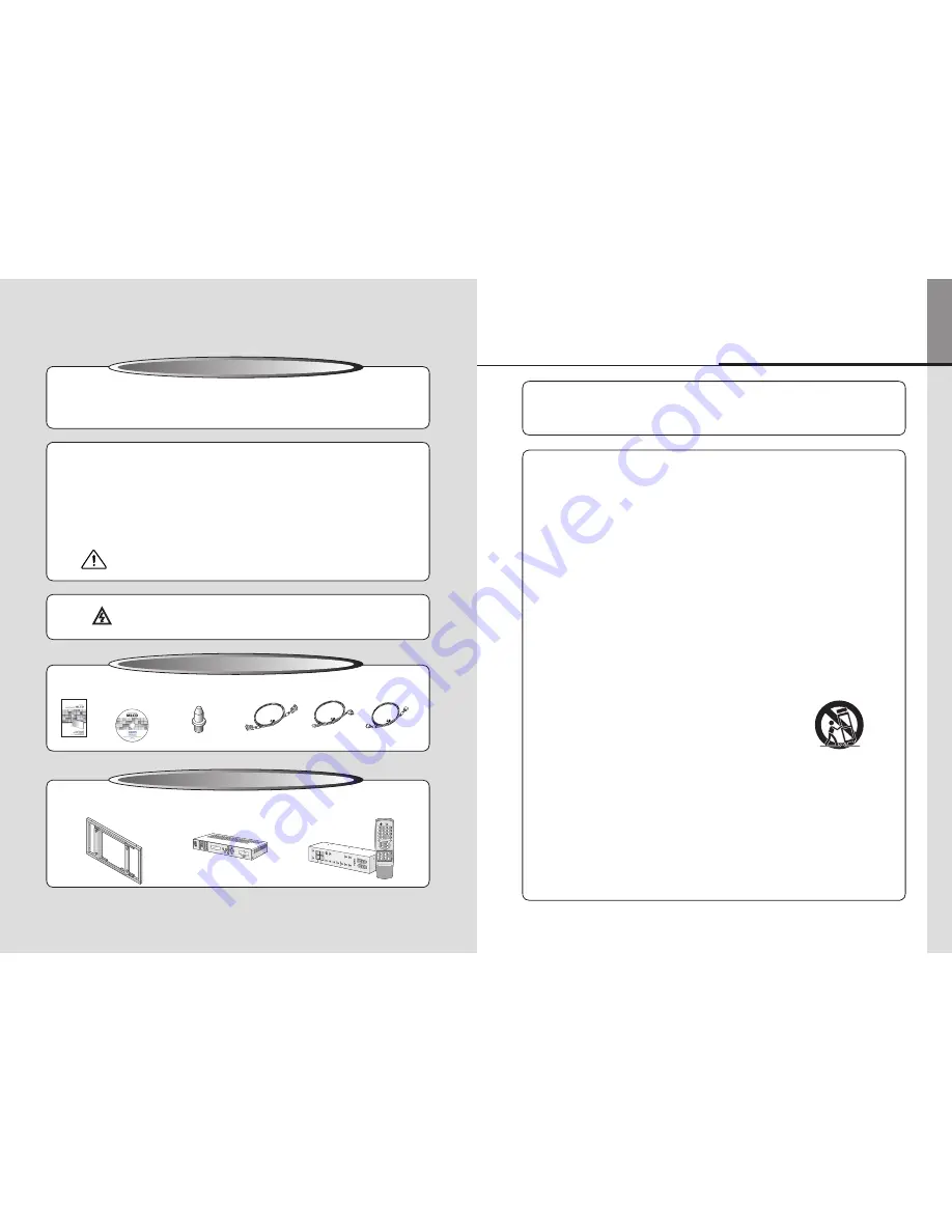
User'sManual
GuidePin(4pcs)
RS-232CCable
DVI-DCable
PowerCable
Supplied Accessories
Multi-ScreenControl
System(MSCS)
Notice to users
Class A digital device
It is a device designed for business purpose with a safety certificate for electromagnetic interference, which
user should be mindful of.
" Important Safety Instructions"
1) Read these instructions.
2) Keep these instructions.
3) Heed all warnings.
4) Follow all instructions.
5) Do not use this apparatus near water.
6) Clean only with dry cloth.
7) Do not block any ventilation openings. Install in accordance with the manufacturer’s instructions.
8) Do not install near any heat sources such as radiators, heat registers, stoves, or other apparatus
(including amplifiers) that produce heat.
9) Do not defeat the safety purpose of the polarized or grounding-type plug. A polarized plug has
two blades with one wider than the other. A grounding type plug has two blades and a third
grounding prong. The wide blade or the third prong are provided for your safety. If the provided
plug does not fit into your outlet, consult an electrician for replacement of the obsolete outlet.
10) Protect the power cord from being walked on or pinched particularly at plugs, convenience
receptacles, and the point where they exit from the apparatus.
11) Only use attachments/accessories specified by the manufacturer.
12) Use only with the cart, stand, tripod, bracket, or table specified by the
manufacturer, or sold with the apparatus. When a cart is used, use
caution when moving the cart/apparatus combination to avoid injury
from tip-over.
13) Unplug this apparatus during lightning storms or when unused for long periods of time.
14) Refer all servicing to qualified service personnel. Servicing is required when the apparatus has
been damaged in any way, such as power-supply cord or plug is damaged, liquid has been
spilled or objects have fallen into the apparatus, the apparatus has been exposed to rain or
moisture, does not operate normally, or has been dropped.
The symbol in figure 21 shall be shown adjacent to the text of item 12 above.
Optional Accessories
MAIN FRAME
(refer to page 16~17)
DVI Converter
(ODC-10000)
REMOTE CONTROL
ON
OFF
INFO
A
SET
DVIC1
DVIC2
INFO
AUTO
VIDEO S-VIDEO HDSDI
DVI
PC
DTV
HDMI
B
BROADCAST
ID SETTING
ON
OFF
1
2
3
4
5
6
7
8
0
9
DVI 1
DVI 2
OUTPUT
FUNCTION
DVI CONVERTER INPUT
New MFC SET
MLCD


