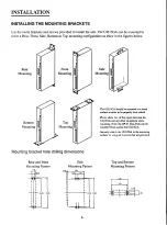
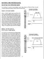

IMPROVING THE ACCURACY OF THE HOME POSITION
PLC
-
STARTUI21SGA
2-PHASE
STEP
MOTOR
TABLE
CCW
C
C
W
DI
SC
WITIL SLIT
RESET
T M °
IIIHOMELS OS-STOP DCWLS
S-STOP
P„OT0SELISORlirWLS
OUTPuT
'VW
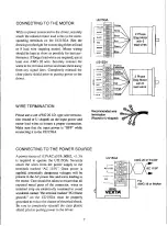
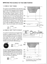
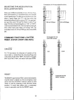
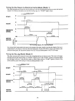
1) HOMELS "AND" TIMING
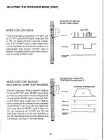
The accuracy of your HOMELS can be improved if
you define the mechanical home position to be the
logical "AND" of the HOMELS and the TIMING
(Phase 0) output of the UI215GA driver. Since the
step motor phase excitation sequence is repeated
every four full steps (eight half steps), this signal will
be output every 7.2°( 3.6° for 0.9°/step motors).
When the step motor is in the "Phase CI" position, the
TIMING indicator on the front panel will illuminate
and pin '34 on connector CN 1 will be turned "ON".
The UI215GA will automatically be in the "Phase 0"
position when it is first powered-up. By using the
logical "AND" of HOMELS and TIMING, any "dead-
band" or "slop" in your switches will be eliminated.
AND
FUNCTI
ON
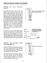
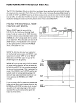
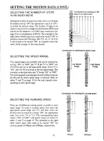
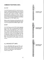
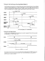
2) HOMELS "AND" PHOTO SENSOR
The mechanical home position can also be set more
accurately by using the logical "AND" o f the
HOMELS and PHOTO SENSOR. By cutting a slit
into a round, flat disc and using it to turn the photo
sensor output "ON" and "OFF", the mechanical
home position of your system can be made more
accurate by making it the logical "AND" of the
HOMELS and the PHOTO SENSOR output.
SLIT
AND FUNCTION
RESET
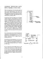
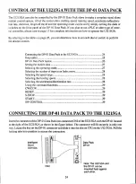
The most accurate positioning method would use
the logical "AND" of HOMELS and TIMING and
the PHOTO SENSOR. The disc used for the photo
sensor should have a slit of 7.2° (3.6°) cut into it for
the most accuracy. This method is very effective
when used in ballscrew applications.
AND FUNCTION
CW
CCW
MOTOR
MOTION
START
S-STOP
HOMELS
TIMING
RESET
Li
1.0 7 213 61
20
CW
CCW
MOTOR
MOTION
START
S-STOP
HOMELS
PHOTO
SENSOR
RESET
I..
360'
1
*The slit should be 7.2° for 1.8°/step motors
and 3.6° for 0.9°/step motors.


