

UI215GA
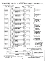
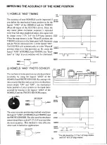
CONNECTING TO THE MOTOR
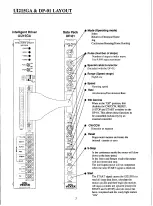
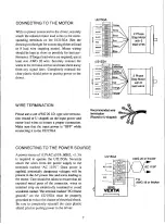
With no power connected to the driver, securely
attach the colored motor lead wires to the corre-
sponding terminals on the UI215GA (See the
drawings to the right for connecting either a 6 lead
or 8 lead wire stepping motor). Motor wiring
should be kept as short as possible for best per-
formance. If longer lead wires are required, use at
least size AWG 20 wire. Securely connect the
wires to the terminal screws and route them away
from any signal lines. Completely reinstall the
clear plastic shield prior to putting power to the
driver.
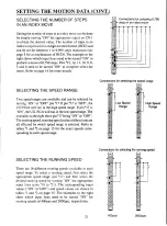
WIRE TERMINATION
Please use a size AWG 20 I.D. type wire termina-
tion (round or U-shaped) on the input power and
motor lead wires to ensure a proper connection.
Make sure that the input power is "OFF" while
connecting it to the UI215GA
— Y E L L O W
WHITE
BLACK
RED
GREEN
— B L U E
UI215GA
— Y E L L O W
WHITE
BLACK
RED
GREEN
— B L U E
Yellow
White/Black
VVhiteiOrang•
Recommended wire
termination
(Round or U-shaped)
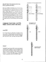
CONNECTING TO THE POWER SOURCE
A power source of 115VAC ±10%, 60HZ, <1.3A
is required to operate the UI215GA. Securely
attach the wires from the power supply to the
terminals marked "AC 115V". Once power is
applied, potentially dangerous voltages will be
present in the AC power line and wires leading to
the motor. Care should be taken to ensure that all
exposed metal parts of the connector, wires or
terminal strip are electrically insulated to avoid
accidental contact. The terminal marked "FG (frame
ground)" on the UI215GA must be properly
grounded to reduce the chance of electrical shock.
Be sure to completely reinstall the clear plastic
shield prior to putting power to the driver.
U1215GA
Li
AC 115V
I
FG
2 Phase
Step Motor
with 6
lead wires
2 Phase
Step Motor
with 8
lead wires
AWG 20 or thicker
SUPER
VEXTA
AC 115V
FG
AWG 18 or thicker
7


