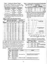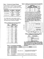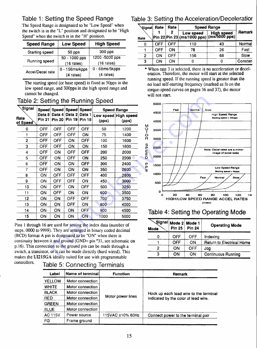
Table 1: Setting the Speed Range T a b l e 3: Setting the Acceleration/Deceleratior
Speed Range
Low Speed
High Speed
Starting speed
50 pps
300 pps
Running speed
50 - 1000 pps
(16 rates)
1200 -5000 pps
(16 rates)
Accel/Decel rate
0 - 156ms/kpps
(4
rates)
0 - 68ms/5kpps
(4 rates)
ignal
Rate
Rate
1
Pin 22
Rate
2
Pin 23
Speed Range
Remark
Low speed
(ms/1000 pps)
High speed
(ms/5000 pps)
0
OFF
OFF
110
43
Normal
1
OFF
ON
78
26
Fast
2
ON
OFF
156
68
Slow
3
ON
ON
0
0
Constan
Signal
Rate
of Speed
Speed
Data 8
Pin 21
Speed
Data 4
Pin 20
Speed
Data 2
Pin 19
Speed
Data 1
Pin 18
Speed Range
Low speed
(pps)
High speed
(pps)
0
OFF
OFF
OFF
OFF
50
1200
1
OFF
OFF
OFF
ON
75
1400
2
OFF
OFF
ON
OFF
100
1600
3
OFF
OFF
ON
ON
150
1800
4
OFF
ON
OFF
OFF
200
2000
5
OFF
ON
OFF
ON
250
2200
6
OFF
ON
ON
OFF
300
2400
7
OFF
ON
ON
ON
350
2600
8
ON
OFF
OFF
OFF
400
2800
9
ON
OFF
OFF
ON
450
3000
10
ON
OFF
ON
OFF
500
3250
11
ON
OFF
ON
ON
600
3500
12
ON
ON
OFF
OFF
700
3750
13
ON
ON
OFF
ON
800
4000
14
ON
ON
ON
OFF
900
4500
15
ON
ON
ON
ON
1000
5000
Signal
Mode
Mode 2
Pin 25
Mode 1
Pin 24
Operating Mode
0
OFF
OFF
Indexing
1
OFF
ON
Return to Electrical Home
2
ON
OFF
Jog
3
ON
ON
Continuous Running
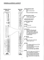
Label
Name of terminal
Function
Remark
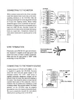
YELLOW
Motor connection
Motor power lines
Hook up each lead wire to the terminal
indicated by the color of lead wire.
WHITE
Motor connection
BLACK
Motor connection
RED
Motor connection
GREEN
Motor connection
BLUE
Motor connection
AC 115V
Power source
115VAC ±10% 60Hz
Connect power to the terminal pair
FG
Frame ground
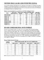
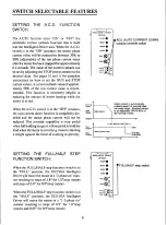
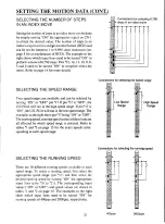
The Speed Range is designated to be "Low Speed" when
the switch is in the "L" position and designated to be "High
Speed" when the switch is in the "H" position.
The starting speed (or base speed) is fixed at 50pps in the
low speed range, and 300pps in the high speed range and
cannot be changed.
Table 2: Setting the Running Speed
Pins 1 through 16 are used for setting the index data (number of
steps, 0000 to 9999). They are arranged in binary coded decimal
(BCD) format A pin is designated to be "ON" when there is
continuity between it and ground (GND= pin "31, see schematic on
p.16). This connection to the ground pin can be made through a
switch, a transistor, or it can be made directly (hard wired). This
makes the U1215GA ideally suited for use with programmable
controllers. Ta b l e 5: Connecting Terminals
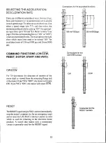
* When rate 3 is selected, there is no acceleration or decel-
eration. Therefore, the motor will start at the selected
running speed. If the running speed is greater than the
no load self-starting frequency (marked as fs on the
torque-speed curves on pages 36 and 37), the motor
will not start.
017-0
O
M
M
T
O
M
0
-i
O3
5 0 0 0
4 5 0 0
4 0 0 0
3 5 0 0
3 0 0 0
2 5 0 0
2 0 0 0
1 5 0 0
1 0 0 0
5 0 0
0
Fast N o r m a l I S l o w
High S p e e d R a n g e
Starting s p e e d . 3 0 0 p p s
Note: D e c a l r a t e s a r e a mirror
i m a g e o f accel rates
L o w S p e e d R a n g e
91arlIng s p e e d S O p p e
Fast N o r m a l S l o w
0
2
0
4
0
6
0
8
0
1 0 0 1 2 0 1 4
HIGH/LOW SPEED RANGE ACCEL RATES
( m s e c )
Table 4 Setting the Operating
Mode
15

