background image

Acme Packet 6100 Hardware Installation Guide

 11

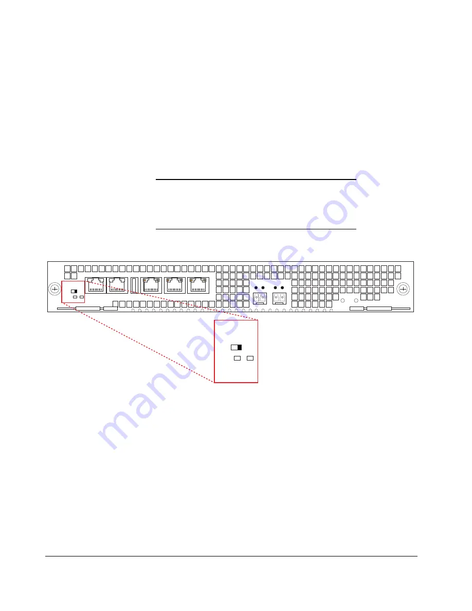
System Power 
Switch - STBY/ON 

The System Power switch enables you to control the power to the Acme Packet 
6100. This is useful when it is desirable to shut off power to the Acme Packet 
6100 without having to unplug the power cord. The Acme Packet 6100 has no 
other power switches. The System Power switch, located on the front panel of 
the NIU, has the following switch settings: 

STBY — when selected, the Acme Packet 6100 powers down. While the 
system is in standby mode, the power supply remains active, and the fans 
inside of the power supply run as necessary. The fans in the front of the 
chassis do not run. This convenient feature enables the system to be shut 
down without having to withdraw the power supply or disconnect the 
power supply cord. 

ON — applies power to the Acme Packet 6100. This switch position is used 
during normal operation. 

Caution

The System Power switch should remain in the ON position at 
all times. Do not touch a System Power switch unless 
specifically instructed to do so by your customer support 
representative.

Mgmt 2

Mgmt 1

Mgmt 0

USB

Alarm

Console

System

Power

On

Stby

Stby

Dis

System

Power

On

Stby

Stby

Dis

LINK ACT

LINK ACT

PWR

H/S

Figure 2 - 18. System Power Settings on the NIU Front Panel 

USB Port 

The USB port, located on the Acme Packet 6100 front panel, is reserved for 
software-enabled applications. 

Summary of Contents for Acme Packet 6100

Page 1: ...Acme Packet 6100 Hardware Installation Guide Regulatory Model AP6100 January 2014...

Page 2: ...icense terms and license restrictions applicable to the programs No other rights are granted to the U S Government This software or hardware is developed for general use in a variety of information ma...

Page 3: ...Battery Warning 2 ESD Safety 2 Environmental Safety and Regulatory Certifications 3 2 Component Overview 5 Chassis 5 System Processor 7 System Control Panels 7 Network Interface Unit 10 Power Compone...

Page 4: ...HA Deployments 52 5 Startup 55 Introduction 55 Creating a Console Connection 55 Powering On the Acme Packet 6100 56 Initial Log On 56 6 Maintenance Introduction 59 Introduction 59 System Shut Down 59...

Page 5: ...ifications 90 Environmental Specifications 91 Connector Specifications 91 Optical Transceiver Interface Module Specification 92 Regulatory Specifications and Certifications 93 WEEE Directive Complianc...

Page 6: ...vi Acme Packet 6100 Hardware Installation Guide...

Page 7: ...onents The Acme Packet 6100 Hardware Installation Guide describes Component Overview Graphic Display and its Usage System Installation Start up Maintenance Safety Specifications Glossary Audience This...

Page 8: ...viii Acme Packet 6100 Hardware Installation Guide...

Page 9: ...around the Acme Packet 6100 clean and clutter free System Maintenance Aside from the fan module fan filter power supply and NIUs there are no user serviceable parts inside the Acme Packet 6100 Only p...

Page 10: ...de a grounded rack structure or local grounding bus bar When installing the Acme Packet 6100 in an equipment rack always make the ground connection first and disconnect it last upon un installation Us...

Page 11: ...painted Paint can hinder proper grounding If your equipment rack is painted you should ground the system to some other reliable place or remove a small portion of paint for proper grounding Use a grou...

Page 12: ...4 Acme Packet 6100 Hardware Installation Guide...

Page 13: ...ions the system chassis is outfitted with left and right chassis mounted slide rails One rail is secured to each side of the chassis which slides into another rail that is attached to the inner posts...

Page 14: ...6 Rack Mounted Slide Rail rear mounting point at left Figure 2 7 Chassis Mounted Slide Rail Once the slide rails are installed on the chassis and on the equipment rack the chassis can be installed in...

Page 15: ...CPU The Acme Packet 6100 processor module CPU is located on the main board of the Acme Packet 6100 This processor module handles both the management and signal processing within the system The CPU int...

Page 16: ...y rebooting the Acme Packet 6100 After the reset button is released the Acme Packet 6100 begins its boot sequence and loads the configured software file The Acme Packet 6100 reset pushbutton button is...

Page 17: ...o navigate through the menus and information visible on the graphic display Intake Fans Five individual intake fans keep the Acme Packet 6100 cool by blowing air through the front panel and exhausting...

Page 18: ...Packet 6100 you can exchange an NIU by removing and replacing it Upon NIU removal the Acme Packet 6100 enters an Out of Service state After you reinsert the NIU and connect to the ACLI you must reboo...

Page 19: ...n as necessary The fans in the front of the chassis do not run This convenient feature enables the system to be shut down without having to withdraw the power supply or disconnect the power supply cor...

Page 20: ...s Mgmt 2 Mgmt 1 Mgmt 0 USB Alarm Console System Power On Stby Stby Dis LINK ACT LINK ACT PWR H S Console Figure 2 20 Console Port Console port communication is used for administration and maintenance...

Page 21: ...ket 6100 and the console adapter Figure 2 21 Console Adapter Alarm Port The alarm port on the NIU is a flexible interface that closes a circuit when a specific alarm level becomes active on the Acme P...

Page 22: ...tical Table 2 3 Acme Packet 6100 Alarm Port Pin Outs Pin Number Signal Name Description 1 Minor Alarm Pin 1 2 Minor Alarm Pin 2 3 Major Alarm Pin 1 4 Major Alarm Pin 2 5 Critical Alarm Pin 1 6 Critica...

Page 23: ...or use Set up the management interfaces using the physical and network interface configuration elements Refer to the System Configuration chapter of the Acme Packet Configuration Guide for details Onc...

Page 24: ...Components Acme Packet offers AC or DC power options for the Acme Packet 6100 The power supplies are user replaceable hot swappable components Each power supply is accessed from the rear panel of the...

Page 25: ...malfunctioning power supply must be removed and replaced as soon as possible If the Acme Packet 6100 starts up with only one power supply it will not generate an alarm AC Power The auto sensing AC po...

Page 26: ...to Lock Unlock Power Supply to Acme Packet 6100 Figure 2 29 Acme Packet 6100 DC Power Supply DC Power Cords A DC power cord ships with each DC power supply A DC power cord must be 3 conductor 10 AWG m...

Page 27: ...is powered by a connector that joins the fan to the motherboard when screwed into the chassis Figure 2 30 Acme Packet 6100 Cooling Fans The Acme Packet 6100 automatically adjusts fan speed based on t...

Page 28: ...ne for monitoring bearer QoS metrics The signaling processor subsystem is comprised of the host processor subsystem and associated memory noted in red in the diagram The session control functions incl...

Page 29: ...tion buttons are located to the right of the display These are used to scroll through display menus and select the information to view on the graphic display Alarm Alarm Power Silence Acme Packet AP61...

Page 30: ...ber and type of alarms appear on the Acme Packet 6100 graphic display which indicates either a link alarm or a hardware alarm For example if there are two link alarms present on the Acme Packet 6100 t...

Page 31: ...g Through Menu Categories on the Graphic Display After 30 seconds of displaying a menu option or submenu information without any user input the system automatically returns to the base display during...

Page 32: ...6 Press the Up or Down button to scroll to the RETURN selection 7 Press the Enter button to return to the Top Menu BOOT PARAMS Menu The BOOT PARAMS menu allows you to view the same information config...

Page 33: ...STEM selection 3 Press the Enter button The first screen in the SYSTEM menu is displayed 4 Press the Up or Down button to scroll through the three SYSTEM screens You can press the Enter button on the...

Page 34: ...ENVIRONMENT menu allows you to view information about the hardware s operational status The graphic display presents the following information in the order listed Screen 1 Hardware alarms and Link Ala...

Page 35: ...phic display window of a Acme Packet 6100 in the initial state NET NET SESSION DIRECTOR I Out Of Service State Displays The following example shows the output in the graphic display window of an out o...

Page 36: ...28 Acme Packet 6100 Hardware Installation Guide...

Page 37: ...e already installed in the chassis Table 4 6 Acme Packet 6100 Shipping Contents Location Item Main Shipping Box Acme Packet 6100 chassis Accessory Kit Console adapter AC or DC power cords one per powe...

Page 38: ...Guidelines When preparing to install your Acme Packet 6100 please ensure you do the following Ensure that the installation location has access to adequate power and grounding Separate circuits should...

Page 39: ...the Acme Packet 6100 from power surges voltage spikes and power failures For AC power installations ensure that your UPS can supply power for enough time to save your system data and shut down the sys...

Page 40: ...onents listed in the packing list are present and in good condition If you discover that any of the parts are missing or were damaged in shipment send an email to tac acmepacket com to request assista...

Page 41: ...stallation Guide 33 Equipment rack slide rail part of the slide rail assembly Figure 4 37 Equipment Rack Slide Rail Chassis slide rail part of the slide rail assembly Figure 4 38 Chassis Slide Rail Nu...

Page 42: ...32 x 5 8 8 Phillips Screw 6 32 x 5 16 6 Flat Head Screw 10 32 x 5 16 6 Figure 4 41 Phillips Screws and Flat Head Screws Center mounting flanges 2 for a 2 post rack Figure 4 42 Center Mounting Flanges...

Page 43: ...es to the front of the equipment rack and the bare steel side attaches to the rear of the equipment rack The equipment rack slide rail can expand and contract to accommodate equipment racks of various...

Page 44: ...d Hole Rack 4 Using a 2 Phillips head screwdriver tighten the screws to secure the slide rail to the equipment rack Do not completely torque the screws leave a small amount of play at this time Figure...

Page 45: ...Figure 4 49 Installed Slide Rails in a Tapped Hole Rack Rear Mount Points Installing Slide Rails into a Square Hole Rack This section explains how to mount the Acme Packet 6100 slide rail assembly in...

Page 46: ...ng spacer then through the slide rail flange and finally through the square hole in the rack rail Mounting Spacer 10 32x5 8 Screw Slide Rail Flange Nut Bar Square Hole Rack Figure 4 51 Attaching the S...

Page 47: ...Using a 2 Phillips head screwdriver tighten the screws securely into place Figure 4 54 Installed Slide Rail in a Square Hole Rack Rear Mount Point 10 Torque the screws on the front and back of the ra...

Page 48: ...4 Line up the chassis slide rail with the Acme Packet 6100 side panel Position the large marker hole in the slide rail at the front of the Acme Packet 6100 chassis The remaining three tapped holes in...

Page 49: ...the Acme Packet 6100 chassis remains supported until you have completely installed it into the equipment rack To install the Acme Packet 6100 chassis into the equipment rack 1 Lift the Acme Packet 61...

Page 50: ...old the slide rails to the rack Center Mount 2 Post Chassis Installation The following sections explain how to center mount your Acme Packet 6100 into a 2 post equipment rack Alarm Alarm Power Silence...

Page 51: ...at this procedure for the other side of the Acme Packet 6100 chassis Installing the Chassis into the Rack The Acme Packet 6100 chassis is now ready to be installed into a 2 post equipment rack To prev...

Page 52: ...ement you can remove and replace it with a functioning one Ground and Power Cable Installation The Acme Packet 6100 must be properly grounded to ensure efficient system performance Grounding your Acme...

Page 53: ...6100 chassis The Acme Packet 6100 ships with 2 kep nuts screwed onto the ground terminals You use an 11 32 nut driver to remove and install these kep nuts This section shows you how to install the gro...

Page 54: ...ground connection first and disconnect it last when installing or removing the system from an equipment rack AC Power Cord Installation This section shows you how to install an AC power cord Caution...

Page 55: ...e AC power cords through your rack and cabling system to the power outlets 6 There is no on off switch on these power supplies When you plug them in the power is on and the system will start to boot 7...

Page 56: ...tem Power On Stby Stby Dis OUT IN OUT IN Figure 4 73 Plug in One DC Power Cord 4 Connect the plug from another 3 conductor power cord to the power connector located on the other DC power supply Ala Co...

Page 57: ...rd DB 9 serial port to the Acme Packet 6100 s RJ45 console port Mgmt 2 Mgmt 1 Mgmt 0 USB Alarm Console System Power On Stby Stby Dis LINK ACT LINK ACT PWR H S Figure 4 75 Console Port Chassis Console...

Page 58: ...rnet cables with RJ45 jacks are used for connecting the Acme Packet 6100 management Ethernet ports to your network These ports support 10 100 1000 Mbps speeds Note Keep Ethernet cables separated from...

Page 59: ...cable To prevent serious eye damage never look directly into a fiber optic cable connector or mating adapter Clean all fiber optics before installing them into your network according to prescribed pro...

Page 60: ...les are required for cabling two HA nodes together Rear Panel Cabling You can use one or two connections for HA redundancy support between the two members of an HA node Using two rear interfaces for s...

Page 61: ...Ethernet cable into Mgmt1 on the rear panel of Acme Packet 6100 A The release tab on the RJ45 jack clicks into place when you insert it properly 2 Insert the other end of the cable into the Mgmt1 por...

Page 62: ...a port cabling in an HA node depends on network topology After a switchover between the two Acme Packet 6100 s in an HA node the standby system sends out an ARP message using a configured virtual MAC...

Page 63: ...e terminal hardware and software appropriately Table 5 7 Terminal Application Serial Settings for Use with Console Port Serial Connection Parameter Setting Baud Rate 115 200 bps Date Bits 8 Parity No...

Page 64: ...ACT LINK ACT PWR H S Figure 5 84 System Power Switch Note When operating with redundant power supplies both power supplies must be plugged in either simultaneously or within a few seconds of each oth...

Page 65: ...ng statistics on the Acme Packet 6100 and perform configuration tasks 2 Type enable and press return to enter Superuser mode The prompt to enter the superuser password appears ACMEPACKET enable Passwo...

Page 66: ...58 Acme Packet 6100 Hardware Installation Guide...

Page 67: ...inue uninterrupted but no new calls are admitted After all call processing has stopped you can power off your Acme Packet 6100 Shutting down the system is appropriate when you are replacing a physical...

Page 68: ...le below refer to the ACLI Reference Guide To reboot the Acme Packet 6100 1 Save any configuration changes you have made in the ACLI while in Superuser mode by typing save config Enter ACMEPACKET save...

Page 69: ...lies means to remove power from the system It is imperative that you wait at least 10 seconds between power down and power up to ensure that all components are completely powered down before restartin...

Page 70: ...100s to switch HA states Forcing a switchover renders the currently active Acme Packet 6100 standby and the currently standby Acme Packet 6100 will assume all traffic processing and forwarding as the...

Page 71: ...andby Jun 25 19 04 54 684 Standby to BecomingActive NETNETSBC1 NETNETSBC2 show health Media Synchronized true SIP Synchronized true MGCP Synchronized true H248 Synchronized disabled Config Synchronize...

Page 72: ...unning cfg version Running configuration version is 5 NETNETSBC2 Note While the two running configuration version numbers on the two systems MUST match each other they do not have to match the shared...

Page 73: ...w the safety precautions for the Acme Packet 6100 prior to proceeding To remove the Acme Packet 6100 from an equipment rack 1 Remove the two AC DC power cords from the power supplies in the rear of th...

Page 74: ...n 8 Remove the chassis completely from the slide rails 9 Lift the Acme Packet 6100 out of the equipment rack and move it to an ESD safe location Power Supply Removal and Replacement This section expla...

Page 75: ...Packet 6100 chassis 1 Remove the AC or DC power cables from the power supplies Figure 6 91 Removing the Power Cords 2 With your thumb push the grey locking tab to the left to unlock the power supply...

Page 76: ...the power supply to be installed 2 Locate the empty power supply slot in the chassis 3 Insert the power supply into the empty power supply slot located on the rear panel of the Acme Packet 6100 chass...

Page 77: ...nctioning fan and quickly replace it with a functioning one to prevent the system from overheating The Acme Packet 6100 air filter is located behind the Bezel and is a Field Replaceable Unit Caution A...

Page 78: ...SD safe location Figure 6 97 Removing the Fan Install Individual Fans To obtain a replacement fan contact your customer support representative Replacing the fan is the reverse process as removing it T...

Page 79: ...e other magnetic side attaches Figure 6 101 Replacing the Front Bezel 4 The replacement fan and bezel are installed into the Acme Packet 6100 Maintaining the Cooling Components The Acme Packet 6100 ai...

Page 80: ...ng the Cooling Components To clean the fan module 1 Remove the fan module from the chassis 2 Spray compressed air into the fan module to dislodge and blow away any contaminants and clean out the four...

Page 81: ...used air filter 6 Gently wipe the front fan bezel that contains the perforated air inlets with a clean dry cloth You can alternatively remove the fan bezel from the system and use compressed air to cl...

Page 82: ...ids to clean the perforated air inlets on the front of the chassis 9 Install the front bezel onto the Acme Packet 6100 by attaching the magnetic bezel to one side of the chassis front and then pivot t...

Page 83: ...on all connections 2 Using a 2 Phillips screwdriver unscrew the two captive thumbscrews located on each side of the NIU The screws are spring loaded and will push forward but they will not fall out o...

Page 84: ...Place the NIU in an antistatic bag while it remains outside of the Acme Packet 6100 NIU Replacement To install an NIU into the Acme Packet 6100 chassis 1 Locate the NIU 2 Ensure that the ejection leve...

Page 85: ...ide rails in the NIU bay of the system chassis Figure 6 113 Installing the NIU 6 Continue sliding the card into the chassis until the ejection levers catch the chassis At this point the ejection lever...

Page 86: ...receptacle for the LC duplex fiber optic connectors Optical transceivers are hot swappable and may be replaced while the Acme Packet 6100 is powered on Leave the NIU in the Acme Packet 6100 as you ex...

Page 87: ...6 10 Gigabit Multi Mode SFP Transceiver Black Bale Clasp Latch The single mode SFP transceiver for the Acme Packet 6100 features a blue clasp latch Figure 6 117 10 Gigabit Single Mode SFP Transceiver...

Page 88: ...GB Yellow Fiber Optic Cable for Use with LX Transceivers Caution To prevent damage to the optical lens Acme Packet recommends that the protective dust cover stay on the optical transceiver port when t...

Page 89: ...t will pivot downwards on its hinge Figure 6 121 Lowering the FSP Bale Clasp Latch 3 Holding the extended bale clasp latch with one hand use your other hand to pull the optical transceiver fully out o...

Page 90: ...tical transceiver into the SFP socket on the NIU Figure 6 123 Inserting the SFP Optical Transceiver into the SFP Socket 2 Press on the face of the SFP optical transceiver to seat it with the socket Fi...

Page 91: ...tage Physical interface cards Each alarm is assigned a severity level depending on the details of the fault Table 6 8 Descriptions of Alarm Severity Levels Alarm Severity Description Minor Functionali...

Page 92: ...s operating between 75 and 90 while the other two fans are operating at normal speed Fan failure Fan speed XXXX XXXX XXXX where xxxx xxxx xxxx is the Revolu tions per Minute RPM of each fan on the fan...

Page 93: ...Cause s Log Message Graphic Display Window Message PLD VOLTAGE ALARM 2P5V 2 5 Volt Rail 65544 MINOR EMERGENCY Voltage 2 5V CPU has minor alarm Voltage 2 5V CPU has emergency alarm the system should s...

Page 94: ...alarming links LINK DOWN ALARM 10GIGPORT 131075 MAJOR 10 GigE S0P0 link down Slot 0 port 0 DOWN X LINK ALARMS LINK UP ALARM 10GIGPORT 131109 MINOR 10 GigE S0P1 link up Slot 0 port 1 UP X LINK ALARMS...

Page 95: ...xample Log Message Graphic Display Message SFP REMOVED GIGPORT 0 65568 CRITICAL S0P0 SFP Removed Slot 0 Port 0 SFP Removed SFP INSERTED GIGPORT 0 65564 CRITICAL S0P0 SFP Inserted Slot 0 Port 0 SFP Ins...

Page 96: ...88 Acme Packet 6100 Hardware Installation Guide...

Page 97: ...1U Width 17 10 43 43 cm mounting ear width 19 48 26 cm Depth 20 50 8 cm mounting slide bar depth Weight approximately 20 5 lbs 9 30 kg fully loaded AC Power Supply Physical Dimensions This table list...

Page 98: ...e input circuit fuse and cable size requirements for the Acme Packet 6100 Table 7 22 Acme Packet 6100 Power Supply Input Circuit Fuse Requirements Power Circuit Fuse Rating Power cable size 120 VAC 15...

Page 99: ...non condensing operat ing conditions Maximum Altitude The Acme Packet 6100 is required to operate below the maximum altitude of 10 000 feet Air Flow 100 CFM Heat Dissipation 500W 3796 BTU hr typical...

Page 100: ...cifications Specification Multi Mode SX Fiber Module Single Mode LX Fiber Module Wavelength 850 nm 1330 nm Laser Type VCSEL FP Fiber type Transmis sion Distance 0 5 to 550 m 50 m 0 5 to 550 m 62 5 m 0...

Page 101: ...a Class A digital device pursuant to Part 15 of the FCC Rules These limits are designed to provide reasonable protection against harmful interference when the equipment is operated in a commercial en...

Page 102: ...95 EC the WEEE directive became European Union law in February 2004 The goals of the RoHS directive are to reduce the amounts of hazardous materials in EEE Acme Packet is compliant with WEEE offering...

Page 103: ...c Compatibility is the ability of equipment or systems to be used in their intended environment within designed efficiency levels without causing or receiving degradation due to unintentional electrom...

Page 104: ...connection to the Acme Packet 6100 System plugs into an optical transceiver Through this connection light energy is converted into electrical energy PCMCIA Personal Computer Memory Card International...

Page 105: ...ackup battery when primary power is lost UDP User Datagram Protocol provides a simple but unreliable message service for transaction oriented services Each UDP header carries both a source port identi...

Page 106: ...98 Acme Packet 6100 Hardware Installation Guide...

Page 107: ...50 alarm port electrical characteristics 90 91 alarm silence button 21 alarms 83 86 clearing 22 hardware types 83 audience for this document vii B base display 22 battery warning 2 BOOT PARAMS menu 24...

Page 108: ...nstallation hardware 5 graphic display 9 grounding terminals 18 intake fans 9 link LED 15 mounting hardware 5 navigation buttons 9 network management ports 14 NIU 10 power components 16 power supply r...

Page 109: ...pment rack safety 31 ESD precautions 2 3 ESD safety 2 Ethernet ports cable specification 15 labeled diagram 52 recommended cables 15 F fan module replacement 69 70 fan module specifications 90 fan spe...

Page 110: ...52 HA state determination 61 HA switchover 61 hardware temperature alarm information 83 hot swappable parts fan module 69 optical transceiver 78 physical interface card 74 power supplies 66 I input ci...

Page 111: ...cord installation 46 center mount installation 42 chassis installation into a 4 post equipment rack 41 DC power cord installation 47 equipment rack slide rails 35 fan module installation 44 ground ca...

Page 112: ...cal transceiver specifications 92 optical transceiver installing 82 optical transceiver removal replacement 78 80 overview of this document vii P physical dimensions and weight 89 physical interface c...

Page 113: ...60 RETURN 26 S safety guidelines 31 safety precautions 1 safety precautions electrical 1 safety requirements 31 serial adapter See also console adapter serial port flow control 12 SFP presence alarm...

Page 114: ...ode forcing 62 standby mode 61 SYSTEM menu 25 System Power switch 11 system reset 60 T terminal connection 55 tools required 29 V ventilation maintenance 69 voltage alarm information 85 W wancom port...

Reviews: