Rotary chuck - K11-200 ISO 702-2
Version 1.0.5 - 2020-12-09
88
Originalbetriebsanleitung
3442762
│
3442763
│
3442764
GB
K11-
200_I
SO
-702
-2_3
4427
62_3
44276
3_43
3276
4_GB
.f
m
7.6
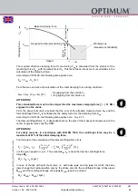
Clamping force-speed diagram - Lathe chuck K11-200
The clamping force to speed diagram shows the calculated centrifugal force with the matching
jaw design as a function for the speed if the chuck jaws do not protrude beyond the outer diam-
eter of the chuck.
7.7
Clamping jaw centrifugal force
To calculate the required tensioning force for processing a workpiece, the centrifugal force of
the clamping jaws must be taken into account.
The permissible speeds can be determined in accordance with VDI Guideline 3106 "Determin-
ing the permissible speed for lathe chucks (jaw chucks). This guideline also allows for the resid-
ual tensioning force at a specified speed to be determined.
Speed n [rpm]
Cl
amping
force
F
sp
[ kN ]
Required minimum clamping force 33 %
Tightening torque with key max. 250 Nm
Tightening torque with key 177 Nm
Fc
Centrifugal force in N
m
Mass in kg/set
rs
Centre of gravity distance to the centre of the chuck in
metres
n
Speed min
-1
r
0
Centre of gravity distance to the clamping jaw


