Operation
Version 1.0.5 - 2020-12-09
50
Translation of original instruction
TX4414
EN
T
X
4414
_GB
_4.
fm
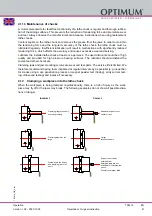
The stand is put on the top slide. The gauge is aligned horizontally and 90° to the top slide. The
top slide is approximately adjusted to the cone angle and the test prod brought in contact with
the cone surface (fix the bedslide). Now the top slide is twisted in a way that the gauge does not
indicate any travel of the pointer over the whole length of the cone (offset over the handwheel
of the top slide).
Then you may start reaming the lathe as described under point 2. The workpiece might be a
flange for lathe chucks or a face plate.
Img. 4-16: Cone setting with stop measure
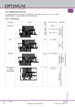
4. By offsetting the tailstock as the cone length is larger than the adjustable stroke of the top
slide.
The workpiece is clamped between two points, therefore center holes are required on the face.
They are to be drilled before removing the lathe chuck. The slaving of the workpiece is per-
formed by a pulling pin and a lathe carrier.
The calculated value "Vr" is the offset measure of the tailstock. The offset is monitored with the
gauge (also the return travel).
For this type of cone machining the lowest speed is used !
Annotation:
In order to check the position of the tailstock axis to the rotation axis, a shaft with two centering-
sis clamped between the points. The stand with the gauge is put on the bedslide. The gauge is
aligned 90° to the rotation axis and horizontally brought into contact with the shaft. The gauge
will pass along the shaft with the bedslide. There must not be any travel of the pointer along the
whole length of the shaft. If a deviation is being shown, the tailstock is to be corrected.
Calculation
Gauge
Advance of depth of cut
Measurin
g and
Feed dire
ction
Calculation:
or
The tailstock offset must not exceed the value
"Vrmax"
as the workpiece
tumbles!
Vr =
Lw
2 x Kv
Vr =
D - d
2 x L
x Lw
Vr
max
=
Lw
50


