Version 1.0.5 - 2020-12-09
28
Translation of original instructions
TX4414
GB
T
X
4414
_GB
_3.
fm
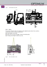
3.6.1
Anchor-free assembly
This must be done by laying down a strong base on each support of the levelling points,
between the foundation and the machine foot.
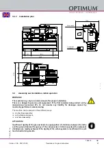
3.6.2
Installation with levelling- damping elements
Optional levelling- damping elements
Attaching of 6 pieces SE2 levelling- damping elements on levelling points between the founda-
tion and machine foot.
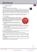
Levelling- damping element dimension
3.6.3
Installation with vibration dampers
Optional vibration dampers
Attaching of 6 pieces SE85 vibration dampers on levelling points between the foundation and
machine stand.
In order to obtain optimum anti-slip protection, the subfloor must be free of oil and grease
before the machine or system is installed.
CAUTION!
The max. load per element refers to the sum of static plus dynamic forces. The machine
must not be moved after the machine has been lowered!
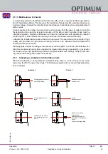
Lift the machine with suitable lifting gear so that the SE85 elements can be pushed underneath.
Insert the levelling screw (1) without the lower large levelling nut (2) from above into the through
hole of the machine foot. Then screw the levelling nut (2) onto the levelling screw from below.
Adjust the levelling screw with the levelling nut until it stands up in the spherical holder of the
vibration damper (3). The screw must be vertical in the through hole. Carry out these preparati-
ons at all support points, and now carefully lower the machine further and level it via the level-
ling nut by holding it against the upper hexagon or lower two-edge of the levelling screw. After
levelling, screw the upper lock nut (4) with washer onto the levelling screw and tighten.
A
B [mm]
C [mm]
D [mm]
E [mm]
SE1
M12
70
10
32
120
SE2
M16
90
12
35
160
SE3
M20
130
12
40
185
Jackscrew
Counternut
A
B
C
D
E


