background image


Seite 8 von 128 

5. Sicherheitshinweise 

VOR INSTALLATION UND INBETRIEBNAHME DAS BE-
NUTZERHANDBUCH UND DIE SICHERHEITSHINWEISE 
AUFMERKSAM LESEN UND BEACHTEN!


Transport 

 USV-Anlage 

nur 

in 

der Originalverpackung transportieren 

(Schutz gegen Stoß und Schlag). 

Aufstellung 

Aufgrund ihres Gewichtes werden für die Installation der USV 
zwei Personen benötigt.  


Dieses Gerät ist für die Installation in einem temperaturkontrol-
lierten Raum, frei von leitfähigen verunreinigten Substanzen 
bestimmt. Spezifizierungen zu den Umgebungsbedingungen 
finden Sie in Kapitel 11.3. 

  Wird die USV-Anlage aus kalter Umgebung in den Arbeits-

raum gebracht, kann Betauung auftreten. Vor Inbetrieb-
nahme muss die USV-Anlage absolut trocken sein. Des-
halb eine Akklimatisationszeit von mindestens zwei Stun-
den abwarten. 

  USV-Anlage nicht in der Nähe von Wasser oder in feuchter 

Umgebung aufstellen. 

  USV-Anlage nicht in direktem Sonnenlicht oder in der Nähe 

von Wärmequellen aufstellen. 

 Lüftungsöffnungen im Gehäuse der USV-Anlage nicht blo-

ckieren. 


Summary of Contents for XANTO RT1000

Page 1: ...www online ups com Manual XANTO RT Series RT 1000 RT 2000 RT 3000 ...

Page 2: ... ONLINE USV Systeme AG Dreimühlenstraße 4 D 80469 München Phone 49 89 2423990 10 Fax 49 89 2423990 20 www online usv de ONLINE UPS Systems S r l Via Edison 12 I 20058 Villasanta Milano Phone 39 039 2051444 Fax 39 039 2051435 www online ups it ONLINE USV Systeme AG Eigenheimstraße 11 CH 8304 Wallisellen Zürich Phone 41 44 9452829 Fax 41 44 9453288 www online usv ch ...

Page 3: ...Seite 2 von 128 ...

Page 4: ...2 7 2 2 Potentialfreie Kontakte 22 7 2 3 Slot für optionale Schnittstellenkarten 23 8 Installation 24 8 1 Tower Installation 25 8 1 1 USV Single Tower Installation 25 8 1 2 USV plus Batteriepaket Installation 26 8 2 Rack Installation 27 8 3 Software Installation 27 9 Betrieb 28 9 1 Betriebsarten 28 9 2 Einschalten 29 9 2 1 Normaler Start Eingangsspannung vorhanden 29 9 2 2 Kaltstart Stromausfall 3...

Page 5: ... 2 Batteriewartung 33 10 3 Wechseln der Ausgangssicherung 34 10 4 Funktionsüberprüfung 35 10 5 Fehlersuche 36 11 Technische Daten 38 11 1 Abmessungen Gewicht 38 11 2 Elektrische Spezifikationen 38 11 3 Umgebungsbedingungen 40 11 4 Zertifizierungen 41 12 Garantie 42 ...

Page 6: ...RT 2000 18 Abbildung 5 Rückseite XANTO RT 3000 18 Abbildung 6 Vorderansicht Batteriepaket 19 Abbildung 7 Rückseite XANTO RT Batteriepaket 19 Abbildung 8 Blockschaltbild 20 Abbildung 9 Bodenplatte für Towermontage 25 Abbildung 10 Positionierung der USV 25 Abbildung 11 Bodenplatte mit Verlängerung 26 Abbildung 12 Anschluss Batteriepakete 26 Abbildung 13 Hot Swap Batterie bei XANTO RT 1000 34 ...

Page 7: ...ngszeit mit zusätzlichen Batteriepaketen BP Batteriepaket 19 Tabelle 6 Pinbelegung der RS 232 Schnittstelle 22 Tabelle 7 Pinbelegung der Schnittstelle DB9 Buchse 23 Tabelle 8 Übersicht Schnittstellenzubehör 23 Tabelle 9 Lieferumfang 24 Tabelle 10 Fehlersuche 37 Tabelle 11 Abmessungen Gewicht 38 Tabelle 12 Elektrische Spezifikationen 40 Tabelle 13 Umgebungsbedingungen 40 Tabelle 14 Zertifizierungen...

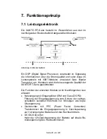
Page 8: ...roni schen Geräte beschädigen können werden somit verhindert Das Doppelwandlerprinzip eliminiert alle Netzstörungen Ein Gleichrichter wandelt den Wechselstrom aus der Steckdose Eingangsspannung in Gleichstrom Dieser Gleichstrom lädt die Batterien und speist den Wechselrichter Der Wechselrich ter wiederum erzeugt aus dem Gleichstrom einen neuen Si nus Wechselstrom mit dem die Verbraucher permanent ...

Page 9: ...urkontrol lierten Raum frei von leitfähigen verunreinigten Substanzen bestimmt Spezifizierungen zu den Umgebungsbedingungen finden Sie in Kapitel 11 3 Wird die USV Anlage aus kalter Umgebung in den Arbeits raum gebracht kann Betauung auftreten Vor Inbetrieb nahme muss die USV Anlage absolut trocken sein Des halb eine Akklimatisationszeit von mindestens zwei Stun den abwarten USV Anlage nicht in de...

Page 10: ...s sene Ausgangskabel nicht länger als 10m sein Keine Haushaltsgeräte wie beispielsweise Haartrockner an den USV Ausgangssteckdosen anschließen Keine Geräte an den USV Ausgangssteckdosen anschlie ßen die die USV Anlage überlasten z B Laserdrucker Leitungen so verlegen dass niemand darauf treten oder darüber stolpern kann Betrieb Netzkabel während des Betriebs nicht von der USV Anlage oder der Steck...

Page 11: ... Vor der Durchführung von Service und Wartungsarbeiten Batterieversorgungskreis trennen und Spannungsfreiheit überprüfen Das Auswechseln der Batterien ist durch Personal mit Sachkenntnis über Batterien und Kenntnis über die gefor derten Vorsichtsmaßnahmen durchzuführen und zu über wachen Unbefugte Personen sind von den Batterien fern zuhalten Achtung Gefahr von Stromschlägen Der Batteriestrom krei...

Page 12: ...explodieren Batterien nicht öffnen oder zerstören Freigesetztes Elekro lyt ist schädlich für Haut und Augen Es kann giftig sein Zum Schutz vor einem Brand darf die Sicherung nur durch einen gleichen Typ mit gleichem Nennwert ersetzt werden USV Anlage nicht auseinanderbauen ...

Page 13: ...XANTO RT 3000 mit Ausgangsklemmenanschluß Außergewöhnlich hohe Leistung Wirkungsgrad 88 Sehr geringe Geräuschentwicklung max 43dB durch geregelte Lüfter Hohe Systemverfügbarkeit Selbstüberwachung und Feh lerdiagnose durch fortschrittliche DSP Technologie Große Eingangsspannungstoleranz mit unempfindlichem Ausgang gegenüber Störungen der Eingangsspannung Passend für alle Anwendungsbereiche mit nich...

Page 14: ... riepaket zum Betrieb notwendig Verlängerte Überbrü ckungszeit durch Parallelbetrieb mehrerer Batteriepakete möglich 3kVA Steuereinheit ohne interne Batterie Externes Batte riepaket zum Betrieb notwendig Verlängerte Überbrü ckungszeit durch Parallelbetrieb mehrerer Batteriepakete möglich 6 2 1 1 Gerätevorderseite Alle Steuereinheiten haben die gleiche Vorderseite Diese stellt Bedien und Anzeigeele...

Page 15: ...ter einschalten Drücken der ON Taste bis ein akusti sches Signal ertönt ca 1 2 Sek und die USV schaltet in den Normalbetrieb 2 Alarm AN AUS im Batteriebetrieb Im Batteriebetrieb ertönt alle 3 Sek ein akustisches Signal Drücken Sie die ON Taste bis ein akustisches Signal er tönt ca 1 2 Sek Anschließend ist das period Signal inaktiv Zum Aktivieren drücken Sie die ON Taste erneut bis ein akust Signal...

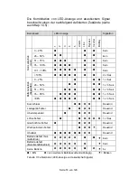
Page 16: ...SV schaltet den Ausgang spannungsfrei Tabelle 1 Bedienelemente Anzeigeelemente Die Bedeutung der Leuchtdioden Anzeige ist in der nachfol genden Tabelle beschrieben BATTERY LED grün USV Betrieb Batteriebetrieb und Batteriespannung innerhalb der Toleranz Dauerlicht LED Blinken Fehlerhafte Batterie oder zu hohe Ladespannung INVERTER LED grün Normalbetrieb Wechselrichterbe trieb Dauerlicht LED Blinken...

Page 17: ...2x Sek 0 25 z z z 1x Sek 26 50 z z z z 1x 3 Sek 51 75 z z z z z 1x 3 Sek 76 95 z z z z z z 1x 3 Sek Batteriebetrieb Kapazität 96 z z z z z z z 1x 3 Sek Kurzschluss z z Dauernd Ladegerät Fehler z z Dauernd Übertemperatur z z Dauernd Lüfter Fehler z z 1x Sek Gleichrichter Fehler z z Dauernd Wechselrichter Fehler z Ï Dauernd Überlast z z z z z z Dauernd Batterie defekt Nor malbetrieb z z Ï Kein Batte...

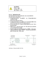
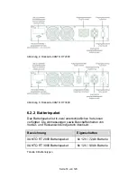
Page 18: ...le Überstromschutzeinrichtung Ausgangssteckdosen ausgeführt als 10A Kaltgerätebuchse sowie Klemmenblock bei 3kVA Steuereinheit Anschlussbuchse für externes Batteriepaket nicht 1kVA Steuereinheit DB9 Buchse männlich male für RS 232 Kommunikation und potentialfreie Kontakte Slot für optionale Schnittstellenkarten SNMP Netzwerk managementkarte basic SNMP Netzwerkmanagement karte professionell USB Kar...

Page 19: ...et Das Batteriepaket ist in zwei unterschiedlichen Versionen verfügbar Die Abmessungen sowie Beschaffenheiten von Vorder und Rückansicht sind jedoch identisch Bezeichnung Eigenschaften XANTO RT 2000 Batteriepaket 6x 12V 7 2Ah Batterie XANTO RT 3000 Batteriepaket 6x 12V 9 0Ah Batterie Tabelle 4 Batterietypen ...

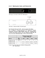
Page 20: ...it bei optionaler Parallel schaltung mehrerer Batteriepakete kann der nachfolgenden Tabelle entnommen werden Es wird dringend empfohlen die max Anzahl an Batteriepaketen nicht zu überschreiten Überbrückungszeit Min bei 50 100 Last Modell Stan dard 1 BPs 2 BPs 3 BPs 4 BPs XANTO RT 1000 18 6 XANTO RT 2000 17 6 52 20 94 37 122 54 XANTO RT 3000 12 5 37 16 55 26 78 40 Tabelle 5 Überbrückungszeit mit zu...

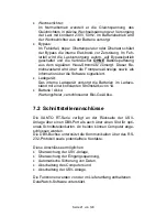
Page 21: ... um Hierdurch wird die herausragende Qualität der XANTO RT Serie gewährleistet Die Funktion der einzelnen Module ist im Nachfolgenden kurz erläutert Netzeingang mit Eingangsfilter EMI und Class D SPD Filterung der Eingangsspannung zum Schutz der nachge schalteten sensiblen Elektronik vor Störungen wie bspw Überspannung Gleichrichter mit PFC Power Factor Correction Transformiert die Eingangsspannun...

Page 22: ...ion über die Software signalisiert Ladegerät Das interne Ladegerät versorgt die Batterien im Ladezu stand mit einer konstanten Stromstärke von 1A Batterie Akku Wartungsfreier verschlossener Blei Gel Akku 7 2 Schnittstellenanschlüsse Die XANTO RT Serie verfügt an der Rückseite der USV Anlage über einen DB9 Port als auch über einen Slot für opti onale Schnittstellenkarten An beiden können Computer a...

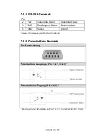
Page 23: ... 3 RxD Empfangene Daten Received data 5 GND Masse ground Tabelle 6 Pinbelegung der RS 232 Schnittstelle 7 2 2 Potentialfreie Kontakte Pin Beschreibung Potentialfreie Ausgänge Pin 1 7 8 9 Potentialfreier Eingang Pin 4 5 Max Spannung Stromstärke an Pins 1 4 5 7 8 und 9 ist 30V DC 10mA ...

Page 24: ...ung ge schlossen 2 Pin 4 5 Potentialfreier Eingang Bei Anlegen einer Hilfs spannung 5 12V DC im Batteriebetrieb für min 20 Se kunden schaltet die USV aus Sonst keine Funktion 3 Pin 8 9 Potentialfreier Ausgang Bei Normalbetrieb ge öffnet bei Batteriebetrieb geschlossen 7 2 3 Slot für optionale Schnittstellenkarten XANTO RT ist mit einem Steckplatz für optionale Schnittstel lenkarten ausgestattet Mi...

Page 25: ...atte für Towermontage 2 X X X Bodenplatte Verlängerung 2 X X 10A Kaltgeräteverlängerung 2 X X X 16A Netzanschlußkabel 1 X Batteriekabel 1 X X Schnittstellenkabel 1 X X X Software DataWatch 1 X X X Bedienungsanleitung 1 X X X Tabelle 9 Lieferumfang 2 Die USV wird durch interne Lüfter mit forciertem Luftstrom gekühlt Gewährleisten Sie dass min 30cm Abstand hin ter der USV zur Verfügung stehen 3 Schl...

Page 26: ...n 8 1 1 USV Single Tower Installation Bitte verwenden Sie die im Lieferumfang enthaltenen Boden platten Entnehmen Sie diese dem Karton und fügen Sie sie wie nachfolgend abgebildet zusammen Abbildung 9 Bodenplatte für Towermontage Nach dem Zusammenfügen der beiden separaten Komponen ten bitte die USV wie folgt platzieren Abbildung 10 Positionierung der USV ...

Page 27: ... 11 Bodenplatte mit Verlängerung Verwenden Sie das Batteriekabel liegt dem Batteriepaket bei um die USV mit dem Batteriepaket zu verbinden 1 Trennen Sie die USV Anlage vom Stromversorgungsnetz und die Verbraucher von der USV Anlage 2 Verbinden Sie das eine Ende des Batteriekabels mit dem Anschluß für die externe Bat terie an der Rückseite der USV und das andere Ende mit einer beliebigen Buchse an ...

Page 28: ...verteilung unsere optio nalen Montageschienen Art Nr Rack Kit oder schrankher stellerspezifische Montageschienen verwenden 1 Verwenden Sie die im Lieferumfang enthaltenen Monta gewinkel 2 Entfernen Sie die M4x8 Schrauben an beiden Seitenteilen der USV 4 Stück je Seite 3 Befestigen Sie die Montagewinkel mit den zuvor entfern ten Schrauben 4 Plazieren Sie die USV im Rack und fixieren Sie sie 8 3 Sof...

Page 29: ...der USV Anlage mit der Software einstellen 3 Schließen Sie Ihre Computer über die mitgelieferten 10A Kaltgeräteverlängerungskabel an die USV Ausgangs steckdosen an ACHTUNG Schließen Sie keine Geräte an die USV Ausgangssteckdosen an die die USV Anlagen überlasten z B Laserdrucker Schließen Sie keine Haushaltsgeräte an die USV Anlage an 9 1 Betriebsarten XANTO RT verfügt über drei Betriebsarten 1 No...

Page 30: ...sspannung im Normalbetrieb die definier ten Spannungs und oder Frequenztoleranzen bzw tritt ein absoluter Stromausfall auf so schaltet die USV autom und unterbrechungsfrei in den Batteriebetrieb Der Gleichrichter und das Lademodul sind hierbei inaktiv Im Batteriebetrieb leuchten die BATTERY und INVERTER LEDs 9 2 Einschalten Es gibt zwei Möglichkeiten um die USV einzuschalten 9 2 1 Normaler Start E...

Page 31: ...sfall Bei nicht vorhandener Eingangsspannung kann die USV auch autark aus der Batterie gestartet werden Drücken Sie die ON Taste bis ein akustisches Signal ertönt ca 1 2 Sek Jetzt schaltet der Wechselrichter ein und die USV arbeitet in der Betriebsart Batteriebetrieb ACHTUNG An den Ausgangssteckdosen der USV Anlage kann eine Spannung entstehen auch wenn das Versorgungsnetz abgeschaltet oder das Ne...

Page 32: ...haftsbetrieb und stellt die Spannungsversorgung der Last ein Zum absoluten Ausschalten der USV bitte Netzkabel ziehen Nach einer geringen Nachlaufzeit der Lüfter schaltet die USV komplett aus 9 4 Batterietest Während der Betriebsart Normalbetrieb können Sie einen autom Batterietest durchführen um Information über Konditi on Alterungszustand der Batterie zu erhalten Hierzu gibt es zwei Möglichkeite...

Page 33: ...otline anrufen HINWEIS ONLINE Hotline 49 0 89 2 42 39 90 18 DataWatch Software Weiterhin besteht die Möglichkeit den Batterietest ferngesteu ert über die DataWatch Software zu aktivieren Hierzu lesen Sie bitte die separate Bedienungsanleitung auf der Data Watch CD ...

Page 34: ...n die Ladeintervalle auf zwei Monate verkürzt werden 10 2 Batteriewartung Die Batterie ist die Schlüsselkomponente des USV Systems Die Lebenserwartung der Batterie ist beschränkt und maßgeb lich abhängig von der Umgebungstemperatur und Anzahl der Lade Entladezyklen Hohe Umgebungstemperatur und Tief entladung verkürzen die Lebenserwartung erheblich 1 Halten Sie die Umgebungstemperatur auf konst 20 ...

Page 35: ...aus 6 Jetzt können Sie die Batterien wechseln Achten Sie dar auf nur Batterien des selben Typs zu verwenden Schalten Sie alle 3 Blöcke in Reihe Hierzu verbinden sie jeweils den Pluspol der einen Batterie mit dem Minuspol der nachfolgenden so dass eine Gleichspannung von 36V entsteht 7 Zur Montage verfahren Sie jetzt in umgekehrter Reihen folge 10 3 Wechseln der Ausgangssicherung Ausschließlich die...

Page 36: ...rbeiten Liegt ein Ausfall der pri mären Energieversorgung vor muss die USV im Batteriebe trieb arbeiten In beiden Fällen sollte es zu keiner Fehlermel dung kommen Umschalten Simulieren Sie einen Stromausfall Schalten Sie hierzu die primäre Energieversorgung spannungsfrei Die USV muss anstandslos zwischen Normalbetrieb und Batteriebetrieb sie he Kap 9 1 umschalten Nach der Simulation des Stromausfa...

Page 37: ... drücken 3 LINE LED blinkt Eingangsspan nung frequenz außerhalb der Toleranz Eingangsspannung frequenz sowie Ein gangsschutzschalter überprüfen Last ma nuell ausschalten 4 ALARM LED und Last LEDs 1 5 blinken Alarm signal Überlast Unkritische Lasten abschalten 5 Überlast keine Ausgangsspan nung kein Bypass betrieb möglich Abschalten des Ausgangs wegen Bypass Überlast Bypassspannung frequenz außer h...

Page 38: ...ERTER LED blinkt ALARM LED leuchtet Alarmton Wechselrichter Fehler ONLINE Hotline anrufen 12 ALARM LED und LED 5 leuchten Alarmton Gleichrichter Fehler ONLINE Hotline anrufen 13 ALARM LED LED 2 leuchten Alarmton Ladegerät Fehler ONLINE Hotline anrufen 14 XANTO RT 3000 Ausgangsbuchse hat keine Span nung Ausgangssiche rung defekt USV abschalten Aus gangssicherung erset zen Last trennen USV einschalt...

Page 39: ...5 21 5 Tabelle 11 Abmessungen Gewicht 11 2 Elektrische Spezifikationen MODELL XANTO RT 1000 XANTO RT 2000 XANTO RT 3000 LEISTUNG Scheinleistung VA 1000 2000 3000 Wirkleistung W 700 1400 2100 EINGANG Nennspannung V 230V 186 288VAC Frequenz Hz 50Hz 10 Stromstärke max A 3 8 7 8 10 7 Leistungsfaktor 0 99 Nennspannung 100 Wirklast vollständig geladene Batterie Kaltstart ja voreingestellt 50Hz Eingangss...

Page 40: ...sel richter Überlast 125 1 Minute danach Bypassbetrieb Batteriebetrieb Wechsel richter Überlast 105 kein Einfluss Batteriebetrieb Wechsel richter Überlast 105 125 30 Sekunden danach Bereitschaftsbetrieb Batteriebetrieb Wechsel richter Überlast 125 250ms danach Bereitschaftsbetrieb Wirkungsgrad Normalbe trieb 88 Wirkungsgrad Batteriebe trieb 83 Ausgangsbuchse 4x IEC320 C13 4x IEC320 C13 2x IEC320 C...

Page 41: ...agementkarte basic option Netzwerkmanagementkarte professionell option USB Karte option DataWatch Software inklusive Tabelle 12 Elektrische Spezifikationen 11 3 Umgebungsbedingungen MODELL XANTO RT 1000 XANTO RT 2000 XANTO RT 3000 Betriebstemperatur C 0 40 Lagertemperatur C 25 bis 55 Relative Luftfeuchtigkeit 5 95 nicht kondensierend Kühlung aktive Kühlung 2 interne Lüfter Lufteinlass an der Vorde...

Page 42: ...eit EN 50082 1 ESD IEC 61000 4 2 Level 3 Störanfälligkeit IEC 61000 4 3 Level 3 Umschaltzeit IEC 61000 4 4 Level 4 Stromstoß IEC 61000 4 5 Level 4 Oberschwingungen EN 61000 3 2 EN 61000 3 3 Elektromagn Verträglichkeit EN 50091 2 Class B Niederspannungsrichtlinie EN 62040 1 1 CE marked Tabelle 14 Zertifizierungen ...

Page 43: ...NAHMEN ABGESEHEN ÜBERNIMMT ONLINE KEINERLEI AUSDRÜCKLICHE ODER STILLSCHWEIGENDE GA RANTIE EINSCHLIESSLICH DER ZUSICHERUNG HANDELSÜBLICHER QUALITÄT ODER DER EIGNUNG FÜR EINEN BESTIMMTEN ZWECK In einigen Gerichtsbarkeiten ist die Einschränkung oder der Ausschluss still schweigender Garantien untersagt so dass die vorstehenden Einschränkun gen oder Ausschlüsse für den Käufer möglicherweise nicht gelt...

Page 44: ...80469 München Phone 49 89 2423990 10 Fax 49 89 2423990 20 www online usv de ONLINE UPS Systems S r l Via Edison 12 I 20058 Villasanta Milano Phone 39 039 2051444 Fax 39 039 2051435 www online ups it ONLINE USV Systeme AG Eigenheimstraße 11 CH 8304 Wallisellen Zürich Phone 41 44 9452829 Fax 41 44 9453288 www online usv ch ...

Page 45: ...Seite 44 von 128 ...

Page 46: ... 63 7 2 2 Dry contacts 63 7 2 3 Slot for optional interface cards 64 8 Installation 65 8 1 Tower installation 66 8 1 1 UPS single tower installation 66 8 1 2 UPS plus Batterypack installation 67 8 2 Rack installation 68 8 3 Software installation 68 9 Operation 69 9 1 Operating modes 69 9 2 Switching on 70 9 2 1 Normal start input voltage present 70 9 2 2 Cold start power failure 71 9 3 Switching o...

Page 47: ...ge 74 10 2 Battery maintenance 74 10 3 Replacing the output fuse 75 10 4 Operational test 76 10 5 Troubleshooting 77 11 Technical data 79 11 1 Dimensions weight 79 11 2 Electrical specifications 79 11 3 Ambient conditions 81 11 4 Certifications 82 12 Warranty 83 ...

Page 48: ...el 59 Figure 5 XANTO RT 3000 back panel 59 Figure 6 Front view of XANTO RT Batterypack 60 Figure 7 Rear view of XANTO RT Batterypack 60 Figure 8 Block diagram 61 Figure 9 Baseplate for tower installation 66 Figure 10 Positioning the UPS 66 Figure 11 Baseplate with extension 67 Figure 12 Connecting the Batteriepacks 67 Figure 13 Hot swap battery for the XANTO RT 1000 75 ...

Page 49: ... Autonomy time with additional Batteriepacks BP Batterypack 60 Table 6 RS 232 interface pin assignment 63 Table 7 Interface pin assignment DB9 socket 64 Table 8 Overview of interface accessories 64 Table 9 Scope of supply 65 Table 10 Troubleshooting 78 Table 11 Dimensions weight 79 Table 12 Electrical specifications 81 Table 13 Ambient conditions 81 Table 14 Certifications 82 ...

Page 50: ...ations and volt age surges which can damage servers and other electronic equipment are prevented The double converter principle eliminates all mains power disturbances A rectifier converts the alternating current from the socket outlet input voltage into direct current This direct current charges the batteries and powers the inverter On the basis of this DC voltage the inverter generates a sinusoi...

Page 51: ...lled area that is free from conductive and contami nated substances For information about the necessary ambi ent conditions please refer to Section 11 3 Condensation may occur if the UPS system is moved di rectly from a cold to a warm environment The UPS system must be absolutely dry before being started up for the first time Please allow an acclimatisation time of at least two hours Do not instal...

Page 52: ...PS output sockets Do not connect any appliances to UPS output sockets which will overload the UPS e g laser printers Lay cables in such a way that no one can step on or trip over them Operation Do not disconnect the mains cable from the UPS system or the building wiring socket outlet with earthing contact dur ing operation since this would cancel the protective earthing of the UPS system and of al...

Page 53: ...s Unauthorised persons must be kept well away from the batteries Caution risk of electric shock The battery circuit is not isolated from the input voltage Hazardous voltages may occur between the battery terminals and the earth Batteries may cause electric shock and have a high short circuit current Please take the precautionary measures specified below and any other measures necessary when workin...

Page 54: ... Features Installation height of just 2 height units Hot swap battery XANTO RT 3000 with output terminal connection Extremely high performance efficiency 88 Very low noise emissions max 43dB thanks to use of controlled fans High degree of system availability self monitoring and fault diagnosis thanks to advanced DSP technology High input voltage tolerance output impervious to input voltage disturb...

Page 55: ...k required for operation Autonomy time can be ex tended by operating several Batteriepacks in parallel 3kVA control unit without internal battery External Battery pack required for operation Autonomy time can be ex tended by operating several Batteriepacks in parallel 6 2 1 1 Front panel The front panel is the same on all the control units Various indicators and operating controls are available he...

Page 56: ...s and hold down the ON button until you hear an audible signal approx 1 2 secs The USP will switch to normal mode 2 Alarm ON OFF in battery mode An audible signal is emitted every 3 seconds in battery mode Press and hold down the ON button until you hear an audible signal approx 1 2 secs This will deactivate the intermittent sig nal To reactivate it press and hold down the ON button again until yo...

Page 57: ...e UPS will disconnect the voltage from the output Table 1 Operating controls Indicators The following table explains what the LEDs mean BATTERY LED green UPS operation battery operation and battery voltage within toler ances continuous light Flashing LED battery faulty or charging voltage too high INVERTER LED green Normal operation inverter operation continuous light Flashing LED inverter faulty ...

Page 58: ...x sec 0 25 z z z 1x sec 26 50 z z z z 1x 3 sec 51 75 z z z z z 1x 3 sec 76 95 z z z z z z 1x 3 sec Battery mode ca pacity 96 z z z z z z z 1x 3 sec Short circuit z z Continuous Charger fault z z Continuous Overtemperature z z Continuous Fan fault z z 1x sec Rectifier fault z z Continuous Inverter fault z Ï Continuous Overload z z z z z z Continuous Battery faulty normal mode z z Ï None Battery fau...

Page 59: ... male Overcurrent protective device Output sockets in the form of 10A outlet sockets for non heating appliances plus terminal block in the case of the 3kVA control unit Connection socket for external Batterypack does not apply to 1kVA control unit DB9 socket male for RS 232 communication and dry contacts Slot for optional interface cards basic SNMP network management card professional SNMP network...

Page 60: ...2 Batterypack The Batterypack comes in two different versions However both versions are identical in terms of dimensions and ap pearance front and rear Designation Properties XANTO RT 2000 Batterypack 6x 12V 7 2Ah battery XANTO RT 3000 Batterypack 6x 12V 9 0Ah battery Table 4 Battery types ...

Page 61: ...e below lists the extended autonomy times that can be achieved if several Batteriepacks are connected in parallel optional You are strongly recommended NOT to exceed the max number of Batteriepacks Autonomy time min at 50 100 load Model Stan dard 1 BPs 2 BPs 3 BPs 4 BPs XANTO RT 1000 18 6 XANTO RT 2000 17 6 52 20 94 37 122 54 XANTO RT 3000 12 5 37 16 55 26 78 40 Table 5 Autonomy time with addition...

Page 62: ...or quality Below is a brief explanation of the modules and what they do Power input with input filter EMI and Class D SPD Filters the input voltage so that any downstream sensitive electronics are protected against faults such as overloads Rectifier with PFC Power Factor Correction Transforms the input voltage into DC voltage for supplying the battery and inverter DC DC converter Increases the bat...

Page 63: ... software Charger During charging the internal charger supplies the batteries with a constant current of 1A Battery accumulator Maintenance free sealed lead gel accumulator 7 2 Interface connections With the XANTO RT series the back panel of the UPS system is equipped with a DB9 port and a slot for optional interface cards Computers can be connected to either of them The DB9 socket supports commun...

Page 64: ...en Transmitted data 3 RxD Empfangene Daten Received data 5 GND Masse Ground Table 6 RS 232 interface pin assignment 7 2 2 Dry contacts Pin description Floating outputs pins 1 7 8 9 Floating input pins 4 5 Max voltage current at pins 1 4 5 7 8 and 9 is 30V DC 10mA ...

Page 65: ... 4 5 floating input If an auxiliary voltage 5 12V DC is applied for at least 20 seconds when in battery mode the UPS will shut down These pins do not perform any other function 3 Pins 8 9 floating output Open during normal operation closed during battery operation 7 2 3 Slot for optional interface cards XANTO RT is equipped with a slot for optional interface cards This ensures compatibility with t...

Page 66: ...le 2 X X X X X Baseplate for tower installation 2 X X X Baseplate extension 2 X X 10A non heating appliance extension 2 X X X 16A mains cable 1 X Battery cable 1 X X Interface cable 1 X X X Software DataWatch 1 X X X Operating instructions 1 X X X Table 9 Scope of supply 2 The UPS is cooled by means of forced ventilation using internal fans Please ensure a min clearance of 30cm to the rear of the ...

Page 67: ...n 8 1 1 UPS single tower installation Please use the baseplates included in the scope of supply Remove them from the carton and assemble them as shown below Figure 9 Baseplate for tower installation After assembling the two separate components please posi tion the UPS on the baseplates as shown below Figure 10 Positioning the UPS ...

Page 68: ...d Figure 11 Baseplate with extension Use the battery cable supplied with Batterypack to connect the UPS to the Batterypack 1 Disconnect the UPS system from the mains power supply and the loads from the UPS system 2 Connect one end of the bat tery cable to the socket on the back of the UPS for con necting the external battery and the other end to any socket on the back of the bat tery pack Figure 1...

Page 69: ... please use our optional mounting rails order no Rack Kit or alternatively use mounting rails spe cific to the cabinet manufacturer 1 Use the mounting angle included in the scope of supply 2 Remove the M4x8 screws from both side panels of the UPS 4 on each side 3 Attach the mounting angle using the screws you have just removed 4 Mount the UPS in the rack and secure it 8 3 Software installation To ...

Page 70: ...re 3 Connect your computer to the UPS output socket using the 10A appliance extension cable for non heating appli ances supplied with the product CAUTION Do not connect any appliances to UPS output sockets which will overload the UPS e g laser printers Do not connect any household appli ances to the UPS 9 1 Operating modes XANTO RT features three operating modes 1 Normal mode The load is supplied ...

Page 71: ...t up 3 Battery mode If in normal mode the input voltage strays outside the defined voltage and or frequency tolerances or in the event of an absolute power failure the UPS will switch to battery mode automatically and without interruption of supply The rectifier and charger will be rendered inactive In battery mode the BATTERY and INVERTER LEDs light up 9 2 Switching on There are two ways of switc...

Page 72: ... soon as the battery has been fully discharged and after the return of the input voltage The self start function can be deactivated by DataWatch Software 9 2 2 Cold start power failure If no input voltage is present the UPS can also be started independently via the battery Press the ON button until you hear an audible signal approx 1 2 secs This will switch the inverter on and the UPS will operate...

Page 73: ...9 3 2 Switching off in battery mode Press the OFF button until you hear an audible signal approx 1 2 secs The UPS switches off and cuts the power supply to the load 9 3 3 Switching off in bypass mode Press the OFF button until you hear an audible signal approx 1 2 secs The UPS switches to standby mode and cuts the power supply to the load To shut the UPS down completely disconnect the mains cable ...

Page 74: ...ts for 5 seconds If the test detects a faulty battery the test will be interrupted immediately and normal mode will be resumed In the event of a faulty battery please call the ONLINE Hotline at your earliest convenience NOTE ONLINE Hotline 49 0 89 2 42 39 90 18 DataWatch software You can also run a remote battery test via the DataWatch software For information concerning this option please refer t...

Page 75: ...t loca tions subject to high temperatures 10 2 Battery maintenance The battery is the key component of the UPS system The battery has a limited life expectancy which is heavily depend ent on the ambient temperature and the number of charg ing discharging cycles If the battery is used in high ambient temperatures and discharged totally its life expectancy will be shortened considerably 1 Maintain a...

Page 76: ... this connect the positive terminal of the first battery to the negative terminal of the next one and so on in or der to generate a 36V DC current 7 Now follow the above disassembly procedure in reverse to reassemble the battery compartment 10 3 Replacing the output fuse The XANTO RT 3000 is the only model with an output fuse This protects the output sockets against impermissibly high current The ...

Page 77: ...ry mode No fault message should be output in either case Switchover Simulate a power failure by tripping the building wiring fuse The UPS should be able to switch between normal mode and battery mode see Section 9 1 without any problems After simulating the power failure reconnect the mains to the UPS The UPS should then switch back from battery mode to normal mode LEDs While the UPS is in the abo...

Page 78: ...nput protection switch 3 LINE LED flashing Input volt age frequency outside tolerances Check input volt age frequency and input protection switch Dis connect load 4 ALARM LED and Load LEDs 1 5 flashing alarm signal Overload Disconnect non critical loads 5 Overload no out put voltage bypass mode cannot be accessed Output discon nected due to bypass overload Bypass volt age frequency outside toleran...

Page 79: ...ts call ONLINE hotline 11 INVERTER LED flashing ALARM LED lit alarm signal Inverter fault Call ONLINE hotline 12 ALARM LED and LED 5 lit alarm signal Rectifier fault Call ONLINE hotline 13 ALARM LED LED 2 lit alarm signal Charger fault Call ONLINE hotline 14 No voltage at XANTO RT 3000 output socket Output fuse faulty Switch off UPS replace output fuse Isolate load switch on UPS and check output v...

Page 80: ...20 5 21 5 Table 11 Dimensions weight 11 2 Electrical specifications MODELL XANTO RT 1000 XANTO RT 2000 XANTO RT 3000 POWER Apparent power VA 1000 2000 3000 Effective power W 700 1400 2100 INPUT Rated voltage V 230V 186 288VAC Frequency Hz 50Hz 10 Current max A 3 8 7 8 10 7 Power factor 0 99 rated voltage 100 active power load battery fully charged Cold start Yes default 50Hz Input protection Switc...

Page 81: ...ormal mode inverter overload 125 1 minute then bypass mode Battery mode inverter overload 105 Has no effect Battery mode inverter overload 105 125 30 seconds then standby mode Battery mode inverter overload 125 250ms then standby mode Efficiency normal mode 88 Efficiency battery mode 83 Output socket 4x IEC320 C13 4x IEC320 C13 2x IEC320 C13 terminal BATTERY Type CSB GP 1272 F2 CSB GP1272 F2 CSB H...

Page 82: ...ment card basic Optional Network management card professional Optional USB adaptor Optional DataWatch software Included in scope of supply Table 12 Electrical specifications 11 3 Ambient conditions MODEL XANTO RT 1000 XANTO RT 2000 XANTO RT 3000 Operating temperature C 0 40 Storage temperature C 25 to 55 Relative humidity 5 95 no condensation Cooling Active cooling 2 internal fans air inlet on fro...

Page 83: ...ety EN 50082 1 ESD IEC 61000 4 2 Level 3 Susceptibility to interference IEC 61000 4 3 Level 3 Switchover time IEC 61000 4 4 Level 4 Current surge IEC 61000 4 5 Level 4 Harmonics EN 61000 3 2 EN 61000 3 3 Electromag compatibility EN 50091 2 Class B Low Voltage Directive EN 62040 1 1 CE marked Table 14 Certifications ...

Page 84: ...XCEPTIONS AS HEREIN PROVIDED FOR ONLINE MAKES NO GUARANTEES WHETHER EXPLICIT OR IMPLICIT OF ANY KIND INCLUDING IN RESPECT OF ASSURANCES OF STANDARD QUAL ITY OR THE SUITABILITY OF ITS PRODUCTS FOR A SPECIFIC PUR POSE Some jurisdictions do not permit the limitation or exclusion of implicit guarantees with the result that some of the above restrictions or exclusions may not apply to all purchasers SA...

Page 85: ...Seite 84 von 128 ...

Page 86: ...80469 München Phone 49 89 2423990 10 Fax 49 89 2423990 20 www online usv de ONLINE UPS Systems S r l Via Edison 12 I 20058 Villasanta Milano Phone 39 039 2051444 Fax 39 039 2051435 www online ups it ONLINE USV Systeme AG Eigenheimstraße 11 CH 8304 Wallisellen Zürich Phone 41 44 9452829 Fax 41 44 9453288 www online usv ch ...

Page 87: ...Seite 86 von 128 ...

Page 88: ...tenziale zero 106 7 2 3 Slot per schede d interfaccia opzionali 107 8 Installazione 108 8 1 Installazione Tower 109 8 1 1 Installazione dell UPS a singola torre 109 8 1 2 Installazione di UPS e pacco batterie 110 8 2 Installazione in armadio rack 111 8 3 Installazione del software 111 9 Funzionamento 112 9 1 Modalità di funzionamento 112 9 2 Accensione 113 9 2 1 Avvio normale tensione di rete pres...

Page 89: ...ne delle batterie 117 10 3 Sostituzione del fusibile di uscita 118 10 4 Controllo della funzionalità 119 10 5 Risoluzione dei problemi 120 11 Dati tecnici 123 11 1 Dimensioni d ingombro e peso 123 11 2 Caratteristiche elettriche 123 11 3 Condizioni ambientali 125 11 4 Certificazioni 126 12 Garanzia 127 ...

Page 90: ...2 Figura 5 Panello posteriore del sistema XANTO RT 3000 102 Figura 6 Vista frontale del pacco batterie 103 Figura 7 Vista posteriore del pacco batterie per XANTO RT 103 Figura 8 Schema elettrico a blocchi 104 Figura 9 Piastra base per montaggio Tower 109 Figura 10 Posizionamento dell UPS 109 Figura 11 Piastra base con estensione 110 Figura 12 Collegamento dei pacchi batterie 110 Figura 13 Batterie...

Page 91: ...i PB pacco batterie 103 Tabella 6 Assegnazione dei pin dell interfaccia RS 232 106 Tabella 7 Assegnazione dei pin dell interfaccia connettore DB9 107 Tabella 8 Panoramica delle schede d interfaccia opzionali 107 Tabella 9 Oggetto della consegna 108 Tabella 10 Risoluzione dei problemi 122 Tabella 11 Dimensioni d ingombro e peso 123 Tabella 12 Caratteristiche elettriche 125 Tabella 13 Condizioni amb...

Page 92: ...rincipio di funzionamento a doppia conversione elimi na tutti i disturbi di rete Un raddrizzatore trasforma in corrente continua la corrente alternata proveniente dalla presa elettrica tensione di rete in ingresso Questa corrente continua carica le batterie ed alimenta l inverter L inverter a sua volta trasfor ma questa tensione continua in una tensione sinusoidale al ternata con la quale vengono ...

Page 93: ... controllata al riparo da sostanze conduttive e inqui nanti Per le specifiche relative alle condizioni ambientali ve dere la sezione 11 3 Se il sistema UPS viene portato da un ambiente molto freddo nel locale di lavoro può verificarsi un fenomeno di condensa Prima della messa in funzione il sistema UPS deve essere assolutamente asciutto Pertanto è necessario rispettare un periodo di acclimatazione...

Page 94: ...al l UPS non può essere più lungo di 10 metri Non collegare alcun elettrodomestico ad esempio un a sciugacapelli alle prese di uscita dell UPS Non collegare alcuna apparecchiatura che possa sovracca ricare l UPS ad esempio stampante laser alle prese di uscita del sistema Posare i cavi in modo che nessuno li possa calpestare o vi possa inciampare Funzionamento Non estrarre il cavo di alimentazione ...

Page 95: ...re interventi di assi stenza e manutenzione aprire il circuito di alimentazione delle batterie e accertare l assenza di tensione ai morsetti La sostituzione delle batterie deve essere eseguita e con trollata da personale specializzato e a conoscenza delle necessarie misure di precauzione da adottare Persone non autorizzate non devono avere accesso alle batterie Attenzione Pericolo di folgorazione ...

Page 96: ...ttrolita che potrebbe fuoriuscire è nocivo per la pelle e gli occhi e può essere tossico Per la protezione antincendio il fusibile può essere sostitui to soltanto con uno dello stesso tipo e con lo stesso valore nominale Non smontare il gruppo di continuità ...

Page 97: ...Batterie hot swap sostituibili a caldo Collegamento di uscita a morsetto nel modello XANTO RT 3000 Eccezionale efficienza con un rendimento maggiore dell 88 Rumorosità molto bassa max 43dB grazie alla regola zione della velocità delle ventole Elevata disponibilità del sistema autosorveglianza e dia gnostica degli errori con tecnologia DSP avanzata Ampia tolleranza della tensione d ingresso con usc...

Page 98: ...ell autonomia Unità da 2kVA senza batteria interna È necessario un pacco batterie esterno per il funzionamento Estensione dell autonomia mediante collegamento parallelo di più pac chi batterie Unità da 3kVA senza batteria interna È necessario un pacco batterie esterno per il funzionamento Estensione dell autonomia mediante collegamento parallelo di più pac chi batterie 6 2 1 1 Pannello frontale Tu...

Page 99: ... viene e messo un segnale acustico ca 1 2 secon di e l UPS passa in modalità di funziona mento normale 2 Allarme ON OFF in funzionamento a batteria In funzionamento a batteria ogni 3 secondi viene emesso un segnale acustico Preme re il tasto ON finché non viene emesso un segnale acustico ca 1 2 sec Il segnale periodico viene così disattivato Per attivar lo nuovamente premere il tasto ON finché non...

Page 100: ...ri La tabella seguente spiega il significato degli indicatori lumi nosi a diodo LED BATTERY verde Luce continua Funzionamento UPS funzionamento batterie e tensione batterie entro i limiti di tolleranza Luce lampeggiante Malfunzionamento delle batterie o tensione di carica troppo elevata LED IN VERTER verde Luce continua Funzionamento normale funzionam Inverter Luce lampeggiante Malfunzionamento de...

Page 101: ...x sec 0 25 z z z 1x sec 26 50 z z z z 1x 3 sec 51 75 z z z z z 1x 3 sec 76 95 z z z z z z 1x 3 sec Funzionam a batteria capacità 96 z z z z z z z 1x 3 sec Cortocircuito z z Continuo Errore caricabatteria z z Continuo Sovratemperatura z z Continuo Errore ventola z z 1x sec Errore raddrizzatore z z Continuo Errore inverter z Ï Continuo Sovraccarico z z z z z z Continuo Malfunzionamento batt funziona...

Page 102: ...tezione da sovracorrente Prese di uscita IEC 320 a 10A e morsettiera nell unità di controllo a 3kVA Connettore di collegamento per pacco batterie esterno non presente nell unità da 1kVA Connettore DB9 maschio per comunicazione RS 232 e contatti a potenziale zero Slot per schede d interfaccia opzionali scheda SNMP di gestione di rete basic scheda SNMP di gestione di rete professional interfaccia US...

Page 103: ... RT 3000 6 2 2 Pacco batterie Il pacco batterie è disponibile in due diverse versioni Dimen sioni dotazioni e vista frontale e posteriore sono comunque identiche Denominazione Caratteristiche XANTO RT 2000 pacco batterie 6 batterie 12V 7 2Ah XANTO RT 3000 pacco batterie 6 batterie 12V 9 0Ah Tabella 4 Tipi di batterie ...

Page 104: ... seguente riporta i dati relativi aIl estensione dell au tonomia mediante il collegamento parallelo opzionale di più pacchi batterie Si raccomanda di non superare il numero massimo di pacchi batterie indicato Autonomia min al 50 100 del carico Modello Standard 1 PB 2 PB 3 PB 4 PB XANTO RT 1000 18 6 XANTO RT 2000 17 6 52 20 94 37 122 54 XANTO RT 3000 12 5 37 16 55 26 78 40 Tabella 5 Autonomia con p...

Page 105: ...nduttori speciali detti IGBT Insulated Gate Bipolar Transi stor Questa struttura è alla base dell eccezionale qualità che caratterizza i gruppi della serie XANTO RT Di seguito spieghiamo brevemente la funzione dei singoli mo duli Ingresso rete con filtro d ingresso SPD EMI classe D Filtraggio della tensione d ingresso per proteggere l elettro nica sensibile del carico utilizzatore a valle da distu...

Page 106: ...e elettrica Il passaggio in questo stato operativo viene segnalato mediante gli indi catori luminosi sul pannello frontale nonché via software Caricabatterie In fase di carica il caricabatterie interno eroga alle batterie una corrente costante di 1A Batterie Accumulatore al piombo gel ermetico e senza necessità di manutenzione 7 2 Connessioni di interfaccia La serie XANTO RT è dotata sul retro del...

Page 107: ...rasmessi Transmitted data 3 RxD Dati ricevuti Received data 5 GND Massa Ground Tabella 6 Assegnazione dei pin dell interfaccia RS 232 7 2 2 Contatti a potenziale zero Descrizione dei pin Uscite a potenziale zero pin 1 e 7 8 e 9 Ingresso a potenziale zero pin 4 e 5 Tensione Intensità di corrente max ai pin 1 4 5 7 8 e 9 30V CC 10mA ...

Page 108: ...Pin 4 e 5 Ingresso a potenziale zero Applicando una tensione ausiliaria 5 12V CC in funzionamento a batteria per min 20 secondi l UPS si disconnette Altrimenti nes suna funzione 3 Pin 8 e 9 Uscita a potenziale zero Aperta in funziona mento normale chiusa in funzionamento a batteria 7 2 3 Slot per schede d interfaccia opzionali Il gruppo di continuità XANTO RT è dotato di uno slot per l in seriment...

Page 109: ...ggio Tower 2 X X X Piastra base estensione 2 X X Prolunga alimentazione 10A IEC 320 2 X X X Cavo di alimentazione di rete 16A 1 X Cavo batterie 1 X X Cavo d interfaccia 1 X X X Software DataWatch 1 X X X Istruzioni per l uso 1 X X X Tabella 9 Oggetto della consegna 2 Il sistema UPS viene raffreddato mediante circolazione d aria forzata con ventole interne Assicurare di lasciare una distanza libera...

Page 110: ...ne dell UPS a singola torre Single Tower Per l installazione utilizzare la piastra base inclusa nella forni tura Prelevare i componenti dal cartone ed assemblare la piastra base come sotto illustrato Figura 9 Piastra base per montaggio Tower Dopo avere incastrato i due componenti separati collocare l UPS come mostra la figura seguente Figura 10 Posizionamento dell UPS ...

Page 111: ...e per la piastra base fornita assieme al pacco batterie La dimen sione varia a seconda del numero di pacchi batterie aggiuntivi Figura 11 Piastra base con estensione Per collegare l UPS al pacco batterie utilizzare l apposito cavo batterie fornito assieme al pacco batterie 1 Scollegare l UPS dalla rete di alimentazione e le utenze dal sistema UPS 2 Collegare un estremità del cavo batterie al conne...

Page 112: ...una profondità minima di 400mm Per una suddivisione ottimale del peso si raccomanda di uti lizzare le nostre guide di montaggio opzionali Rack Kit o le guide di montaggio specifiche fornite dal costruttore dell arma dio 1 Utilizzare la staffa di montaggio inclusa nella fornitura 2 Rimuovere le viti M4x8 da entrambi i pannelli laterali del l UPS 4 viti per ogni lato 3 Fissare la staffa di montaggio...

Page 113: ...stema UPS con il software 3 Collegare i computer alle prese di uscita dell UPS utiliz zando l apposito cavo prolunga IEC 320 da 10A in dota zione ATTENZIONE Non collegare alle prese di uscita dell UPS appa recchiature che possono sovraccaricare il sistema ad es stampanti laser Non collegare elettrodo mestici al sistema UPS 9 1 Modalità di funzionamento Il gruppo di continuità XANTO RT dispone di t...

Page 114: ...te In questo stato ope rativo sono accessi i LED LINE e BYPASS 3 Funzionamento a batteria Se in funzionamento normale la tensione di ingresso non rien tra più nelle tolleranze di tensione e o frequenza definite o in caso di interruzione totale della corrente l UPS passa automa ticamente nella modalità di funzionamento a batteria In que sto stato il raddrizzatore e il modulo di carica sono disattiv...

Page 115: ... l inverter si avvia automati camente La funzione di autoavvio può essere disattivata 9 2 2 Avvio a freddo mancanza di corrente In caso di assenza della tensione di rete è possibile comun que avviare l UPS dalle batterie Premere il tasto ON finché non viene emesso un segnale acustico ca 1 2 secondi L in verter si attiva e l UPS funziona in modalità di funzionamento a batteria ATTENZIONE Alle prese...

Page 116: ... 9 3 3 Spegnimento in modalità Bypass Premere il tasto OFF finché non viene emesso un segnale acustico ca 1 2 secondi L UPS passa in stand by e inter rompe l alimentazione del carico Per lo spegnimento definitivo dell UPS staccare il cavo di alimentazione di rete Dopo un breve intervallo di ritardo in cui le ventole continuano a girare l UPS si spegne completamen te 9 4 Test delle batterie In moda...

Page 117: ...rotto e il sistema passa in funzio namento normale In caso di malfunzionamento delle batterie contattare subito l Hotline ONLINE NOTA Hotline ONLINE Italia 39 0 39 2051444 Software DataWatch È inoltre possibile attivare in remoto l esecuzione del test bat terie tramite il software DataWatch Per questa operazione consultare il manuale di istruzioni separato sul CD di Data Watch ...

Page 118: ...icarica dovrebbe essere effettuata con maggiore frequenza ogni due mesi 10 2 Manutenzione delle batterie Le batterie sono un componente chiave del sistema UPS La durata prevista delle batterie è limitata e dipende in gran parte dalla temperatura ambiente e dal numero di cicli di cari ca scarica Temperature ambientali elevate e lo scaricamento completo ne riducono sensibilmente la durata 1 Mantener...

Page 119: ...e sostituire le batterie Si raccomanda di utilizzare solo batterie dello stesso tipo Collegare tutti e tre i blocchi in sequenza Per eseguire questa operazione collegare rispettivamente il polo positivo di una batteria con il polo negativo di quella successiva in modo da ge nerare una tensione continua da 36V 7 Per il montaggio eseguire la procedura descritta in ordine inverso 10 3 Sostituzione de...

Page 120: ... di energia l UPS deve passare in funzionamento a batteria In entrambi i casi non deve essere segnalato alcun errore Commutazione Simulare un interruzione della corrente Disinserire quindi l a limentazione di rete primaria L UPS deve passare senza solu zione di continuità tra il funzionamento normale e il funziona mento a batteria vedere la sezione 9 1 Dopo la simulazione di una mancanza di corren...

Page 121: ...nala alcuna tensione in ingresso Interruttore di protezione di in gresso sul retro dell UPS attivato Premere l interruttore di protezione di ingresso 3 Il LED LINE lampeggia Tensio ne frequenza di ingresso fuori tolleranza Controllare la tensio ne frequenza di ingres so nonché l interruttore di protezione di ingres so Disinserire manual mente il carico 4 Il LED ALARM e i LED dei carichi 1 5 lampeg...

Page 122: ...co Se l errore è ancora presente dopo il distacco del carico contattare l Hotline ONLINE 10 LED ALARM LED 3 sono accesi segnale acustico di allarme Sovratemperatura Controllare che non vi sia un sovraccarico che la ventola non sia bloc cata e che la temperatu ra ambiente non superi i 40 C In caso di condizioni operative normali disin serire l UPS lasciare raffreddare per 10 min e ripetere Se il pr...

Page 123: ...i co accendere l UPS e controllare la tensione di uscita Qualora non si noti alcuna differenza contattare l Hotline ONLINE Tabella 10 Risoluzione dei problemi NOTA Hotline ONLINE Italia 39 0 39 2051444 Quando si contatta l Hotline è necessario avere a disposizione le informazioni seguenti Numero di modello e di serie Data di acquisto e di installazione Descrizione dettagliata del problema ...

Page 124: ...11 2 Caratteristiche elettriche MODELLO XANTO RT 1000 XANTO RT 2000 XANTO RT 3000 POTENZA Potenza apparente VA 1000 2000 3000 Potenza efficace W 700 1400 2100 INGRESSO Tensione nominale V 230V 186 288V CA Frequenza Hz 50Hz 10 Intensità di corrente max A 3 8 7 8 10 7 Fattore di potenza verso la rete 0 99 tensione nom 100 carico attivo batteria caricata completamente Avvio a freddo sì preimpostazion...

Page 125: ...rmale so vraccarico inverter 125 1 minuto quindi modalità Bypass Funzionamento a batteria sovraccarico inverter 105 Nessuna influenza Funzionamento a batteria sovraccarico inverter 105 125 30 secondi quindi modalità Stand by Funzionamento a batteria sovraccarico inverter 125 250ms quindi modalità Stand by Rendimento funzionamento normale 88 Rendimento funzionamento a batteria 83 Connettore di usci...

Page 126: ...a di gestione di rete professional opzionale Interfazzia USB opzionale Software DataWatch incluso Tabella 12 Caratteristiche elettriche 11 3 Condizioni ambientali MODELLO XANTO RT 1000 XANTO RT 2000 XANTO RT 3000 Temperatura d esercizio C 0 40 Temperatura di magazzi naggio C da 25 a 55 Umidità relativa 5 95 senza condensa Raffreddamento raffreddamento attivo 2 ventole interne aspirazione aria sul ...

Page 127: ...ostatiche ESD IEC 61000 4 2 livello 3 Immunità ai disturbi IEC 61000 4 3 livello 3 Tempo di commutazione IEC 61000 4 4 livello 4 Transitori di corrente IEC 61000 4 5 livello 4 Oscillazioni armoniche EN 61000 3 2 EN 61000 3 3 Compatibilità elettromagne tica EN 50091 2 classe B Direttiva Bassa Tensione EN 62040 1 1 Marchio CE Tabella 14 Certificazioni ...

Page 128: ... GARANZIE DI COMMERCIABILITÀ O IDONEITÀ PER UNO SCOPO PARTI COLARE Alcuni ordinamenti giuridici non consentono limitazioni o esclusioni delle garanzie implicite pertanto le suddette limitazioni o esclusioni potrebbe ro non essere pertinenti per l acquirente FATTE SALVE LE ECCEZIONI QUI PREVISTE ONLINE DECLINA OGNI RESPONSABILITÀ PER DANNI DIRETTI INDIRETTI SPECIALI ACCIDEN TALI O CONSEQUENZIALI DE...

Page 129: ...Seite 128 von 128 ...

Reviews: