


ONICON Incorporated 727-447-6140
Page 49
www.onicon.com
SYSTEM-40 BTU MEASUREMENT SYSTEM
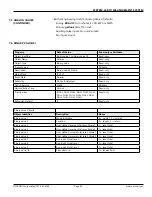
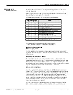
Register
Address
Description
Register
Type
Data
Range
Over
Range
Read/Write
Comments
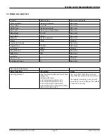
1
Reset User Defined Energy
Total - Single Mode
Coil
NA
NA
Read/Write
Turn coil ON (1) to reset total on System-40.
Turn coil to OFF (0)once reset is complete.
2
Reset User Defined Energy
Total - Mode 1
Coil
NA
NA
Read/Write
Turn coil ON (1) to reset total on System-40.
Turn coil to OFF (0)once reset is complete.
3
Reset User Defined Energy
Total - Mode 2
Coil
NA
NA
Read/Write
Turn coil ON (1) to reset total on System-40.
Turn coil to OFF (0)once reset is complete.
4
Reset User Defined Volume
Total - Single Mode
Coil
NA
NA
Read/Write
Turn coil ON (1) to reset total on System-40.
Turn coil to OFF (0)once reset is complete.
5
Reset User Defined Volume
Total - Mode 1
Coil
NA
NA
Read/Write
Turn coil ON (1) to reset total on System-40.
Turn coil to OFF (0)once reset is complete.
6
Reset User Defined Volume
Total - Mode 2
Coil
NA
NA
Read/Write
Turn coil ON (1) to reset total on System-40.
Turn coil to OFF (0)once reset is complete.
7
Reset Aux Input Total - Input 1 Coil
NA
NA
Read/Write
Turn coil ON (1) to reset total on System-40.
Turn coil to OFF (0)once reset is complete.
8
Reset Aux Input Total - Input 2 Coil
NA
NA
Read/Write
Turn coil ON (1) to reset total on System-40.
Turn coil to OFF (0)once reset is complete.
9
Reset Aux Input Total - Input 3 Coil
NA
NA
Read/Write
Turn coil ON (1) to reset total on System-40.
Turn coil to OFF (0)once reset is complete.
10
Reset Aux Input Total - All
Inputs
Coil
NA
NA
Read/Write
Turn coil ON (1) to reset total on System-40.
Turn coil to OFF (0)once reset is complete.
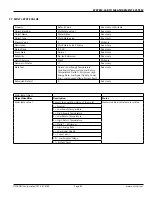
11
Aux Output 1
Coil
NA
NA
Read/Write
Turn coil ON (1) to latch Aux I/O # 1 closed. Turn coil
to OFF (0) to latch I/O # 1 open. Aux I/O #
1 must have been configured as an output at the
factory, and programmed for "MODBUS Coil" in the
commissioning menu.
12
Aux Output 2
Coil
NA
NA
Read/Write
Turn coil ON (1) to latch Aux I/O # 2 closed. Turn coil
to OFF (0) to latch I/O # 2 open. Aux I/O #
2 must have been configured as an output at the
factory, and programmed for "MODBUS Coil" in the
commissioning menu.
13
Aux Output 3
Coil
NA
NA
Read/Write
Turn coil ON (1) to latch Aux I/O # 3 closed. Turn coil
to OFF (0) to latch I/O # 3 open. Aux I/O #
3 must have been configured as an output at the
factory, and programmed for "MODBUS Coil" in the
commissioning menu.
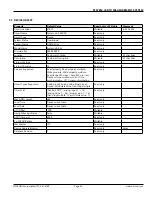
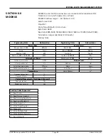
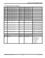
8.1 MODBUS MEMORY MAP
Register
Address
Description
Register Type Data
Range
Over
Range
Read/
Write
Comments
10001
Mode Indication
Discreet Input
1-2
NA
Read Only 1- Indicates Heating Mode; 2- Indicates Cooling Mode
10002
Location
Discreet Input
1-2
NA
Read Only 1- Indicates heating mode; 2- Indicates cooling mode
10003
Mode Single Dual
Discreet Input
1-2
NA
Read Only
1- Indicates meter configured as single mode; 2- indicates
meter configures as dual mode
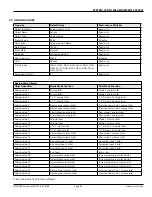
Register
Address
Description
Register Type Register Type
Comments
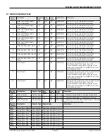
30001
Energy Rate - kBtu/hr Input Register
Floating Point Register (1 of 2)
30002
Energy Rate - kBtu/hr Input Register
Floating Point Register (2 of 2)
30003
Energy Rate - Tons
Input Register
Floating Point Register (1 of 2)
30004
Energy Rate - Tons
Input Register
Floating Point Register (2 of 2)
30005
Energy Rate - kW
Input Register
Floating Point Register (1 of 2)
30006
Energy Rate - kW
Input Register
Floating Point Register (2 of 2)
30007
Energy Rate - MW
Input Register
Floating Point Register (1 of 2)
30008
Energy Rate - MW
Input Register
Floating Point Register (2 of 2)