


ONICON Incorporated 727-447-6140
Page 28
www.onicon.com
SYSTEM-40 BTU MEASUREMENT SYSTEM
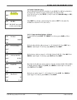
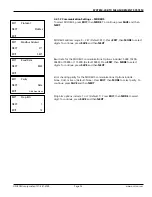
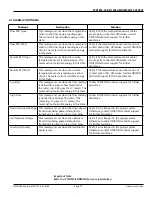
4.2.2.3 Auxiliary Input/ Output (continued)
Default setup displays for one (1) aux pulsed input, one (1) aux pulsed output,
and one (1) analog output.
Aux Config
NEXT
EXIT
EDIT
1 In 1 Out 1 Analog
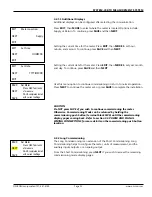
Num Aux Inputs
NEXT
EXIT
EDIT
2
Aux Input 1
NEXT
EXIT
EDIT
Counts
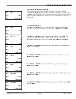
Pulsed Output 2
NEXT
EXIT
SEL
Select Type
Off
Analog Signal
NEXT
EXIT
SEL
4-20 mA
Select Signal
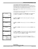
Analog Output
NEXT
EXIT
SEL
Energy Rate
Select Type
Set Meter
Press NEXT edit units
of measure
SAVE completes install
with current settings
NEXT
BACK
SAVE
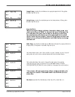
The default auxiliary configurations set as
1 IN, 1 OUT, and 1 ANALOG
. This can
be changed by select
EDIT
. To continue, press
SAVE
, and then
NEXT
.
Press
EDIT
, then
MORE
to select number of aux input. To continue, press
SAVE
and then
NEXT
.
Press
EDIT
, then
MORE
to define aux input 1. To continue, press
SAVE
and then
NEXT
.
Press
EDIT
, then
MORE
to select type of pulse output 2. Options include: Energy
Mode, Volume Mode, Alarm, and Modbus Coil. See 5.3 AUXILIARY OUTPUTS for
more details. To continue, press
SAVE
and then
NEXT
.
Press
EDIT
, then
MORE
to select analog signal as 4-20 mA, 0-5 V or 0-10 V.
Confirm if the jumper are switched into their position. Refer to section 5.5
JUMPER LOCATION and DETAIL for more details. To continue, press
SAVE
, and
then
NEXT
.
Press
EDIT
, then
MORE
to select type of an analog output. Options include:
Energy Rate, Volume Rate, Delta T, Supply Temperature, and Return Temperature.
To continue, press
SAVE
and then
NEXT
.
Use this menu option to save, exit commissioning and return to normal
operation. Press
NEXT
to repeat the meter set, or press
SAVE
to complete the
installation.
Important Note
Screen may vary based on settings.