


ONICON Incorporated 727-447-6140
Page 15
www.onicon.com
SYSTEM-40 BTU MEASUREMENT SYSTEM
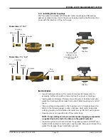
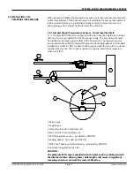
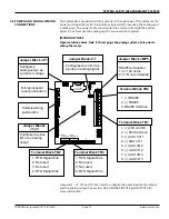
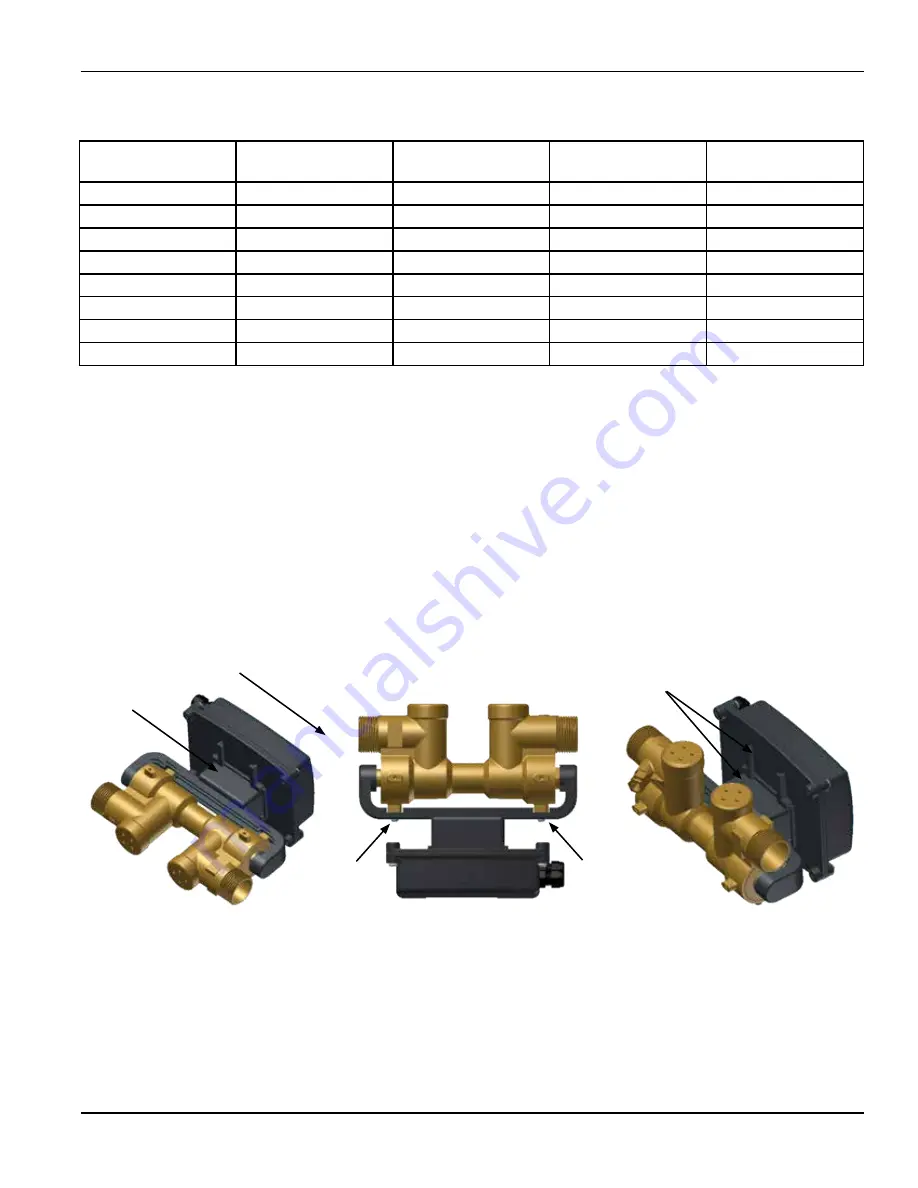
3.3.4 Adjustment and Rotation
For ½” – 1” meter sizes, the enclosure may be rotated around the axis of the flow
sensor into three different positions. To rotate, slide the enclosure off the flow
sensor mounting brackets, remove the two retaining screws and reposition the
mounting brackets as required. Reinstall the enclosure with the display properly
oriented for viewing. Mounting tracks on the back of the enclosure allow for
mounting in any orientation.
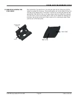
IMPORTANT NOTE
When installing the meter in a vertical pipe with upward flow, you must
rotate the enclosure back plate 180° when rotating the display 90°. To
accomplish this, temporarily remove the four cover screws and rotate the
backing plate.
Sensor
mounting
bracket
Slide enclosure
off of sensor
mounting
bracket
Retaining
Screw
Retaining
Screw
Mounting
tracks
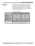
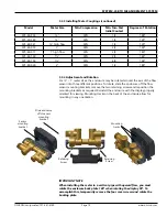
Model
Meter Size
Min. Compression
Min. Turn Past
Initial Contact
Degrees of Rotation
SYS-40-050
½”
30%
1/2
180°
SYS-40-340
¾”
30%
1/3
120°
SYS-40-341
¾” high flow
30%
1/3
120°
SYS-40-010
1”
30%
2/5
140°
SYS-40-011
1” high flow
30%
2/5
140°
SYS-40-130
1¼”
30%
2/5
140°
SYS-40-150
1½”
30%
4/9
160°
SYS-40-020
2”
30%
1/2
180°
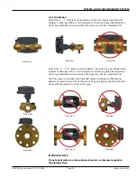
3.3.3 Installing Meter Couplings (continued)