Examples and tips
PROGRAMMING MANUAL
252
Revi
si
on 3.0
/i
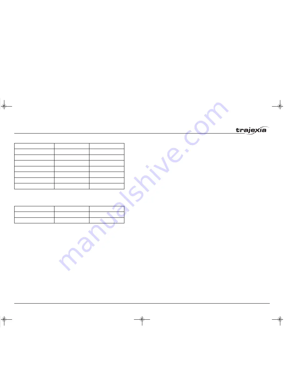
With this default value, the mapping is as follows for the Junma Servo
Driver:
/i
Servo driver inputs mapped into Trajexia I/O space like this are accessed
within the program per axis and cannot be accessed in usual way by using
the
IN
command. The only way you can use these inputs in the program is to
assign them to the axis parameters
DATUM_IN
,
FHOLD_IN
,
FWD_IN
and
REV_IN
. The inputs of the axis Servo Driver are used, depending on the
axis of which the parameters are set.
Example: We have two Sigma-II drivers assigned to controller axes 0 and 3.
For both axes, we want to use input signal CN1-41 to serve as reverse limit
input. We can do this with these commands:
REV_IN AXIS(0) = 29
REV_IN AXIS(3) = 29
Note that even though
REV_IN
parameters for both axes have the same
value 29, the real inputs used are not the same. For axis 0 the CN1-41 input
of the first driver (assigned to that axis) is used, but for axis 3 the same input
CN1-41 of the other driver (the one assigned to axis 3) is used. Therefore
we say that those inputs are accessed per axis, they are not unique for the
whole controller. In general, these two inputs have a different status at the
same time. Also note that neither of these two inputs can be accessed using
the command
IN
. For example the command
IN(29)
returns the status of
controller software input 29 (unique for all axes), which has a different status
than Servo Driver inputs mapped to the same number.
You can find more information on mapping of MECHATROLINK-II Servo
Drivers inputs into the Trajexia I/O space in the Trajexia Programming
Manual, at the BASIC commands
DATUM_IN
,
FHOLD_IN
,
FWD_IN
and
REV_IN
.
DRIVE_MONITOR bit
Connector signal
Trajexia input
6
CN1-44
N/A
7
CN1-45
N/A
8
CN1-46
N/A
12
CN1-40
28
13
CN1-41
29
14
CN1-42
30
15
CN1-43
31
DRIVE_MONITOR bit
Connector signal
Trajexia input
2
CN1-2
26
6
CN1-1
27
I52E-EN-03.book Seite 252 Freitag, 29. Juni 2007 11:55 11


