


Motion controller
71
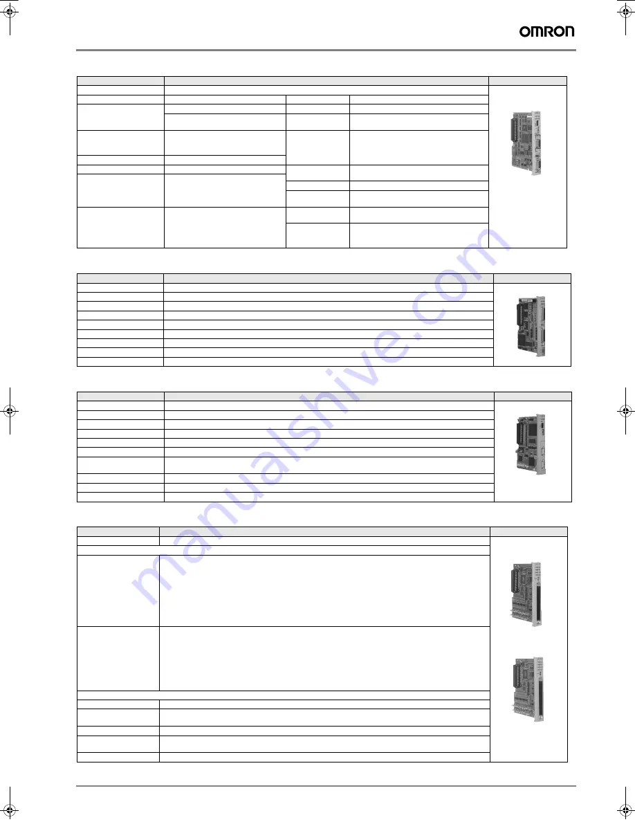
PROFIBUS communication module (261IF-01)
Analogue reference motion control module (SVA-01)
MECHATROLINK-II motion control module (SVB-01)
I/O modules (LIO-01/-02)
Items
Specifications
Appearance
Model
JAPMC-CM2330
Port
For PROFIBUS communication
Port
For RS-232C communication
Functions
DP slave
Interface
One port
Cyclic communication
(DP standard function)
Connector
D-sub 9 pins (female)
Transmission speed
12M/6M/4M/3M/1.5M/750k/500k/
187.5k/93.75k/19.2k/9.6kbps
(automatic detection)
Max. transmission
distance
15 m
Configuration
By PROFIBUS master
Slave address
1 to 64
Transmission
speed
76.8 kbps
I/O processing
Total capacity of IW/OW registers:
64 words
Max. I/O allocation (IN and OUT each):
64 words
Access mode
Asynchronous (start-stop synchronization)
Communication
protocols
MEMOBUS (master or slave)
MELSEC, HostLink, or non-protocol
Diagnostic functions
Display for status and slave status
using the EWS.
I/O error display for SW registers
Media access
control method
1:1
Transmission
format
(can be set)
Data bit length: 7 or 8 bits
Stop bits: 1 or 2 bits
Parity bits: even, odd, or none
Items
Specifications
Appearance
Model
JAPMC-MC2300
Number of axes
2 axes (CN1 & CN2) analogue output and encoder input.
Digital inputs (per axis)
6 inputs, PNP or NPN (including alarm, ready, zero and latch)
Digital outputs (per axis)
6 outputs (including servo_on, alarm_reset, control_mode_select and SEN)
Encoder input (per axis)
Differential line-driver (A,/A,B,/B,Z,/Z). 4 Mpps (before multiplication).
Analog outputs (per axis) 2 outputs ±10 V 16 bits (typically speed and torque references)
Analog inputs (per axis)
2 inputs ±10 V 16 bits
External supply
24 VDC (in CN3)
LED's
RUN (green) ERR(red)
Items
Specifications
Appearance
Model
JAPMC-MC2310
Communication circuits
1 circuit
Communication ports
2 ports
Terminator
External resistor (JEPMC-W6022 required)
Transmission speed
10 Mbps
Communication cycle
0.5ms, 1ms, 1.5ms, 2ms
Number of connecting
stations
21 stations (16 axes for servo drives and inverters) /2 ms, 15 stations (15 axes for servo drives) /1.5 ms,
9 stations (9 axes for servo drives) /1ms, 4 stations (4 axes for servo drives) /0.5 ms
Retry function
Available with MECHATROLINK-II
Slave function
Available with MECHATROLINK-II
Transmission distance
See “MECHATROLINK-II repeater”
Items
Specifications
Appearance
Models
JAPMC-IO2300 (NPN output), JAPMC-IO2301 (PNP output)
Digital I/O
Input signals 16 points (all connected) and 24 VDC±20%, 5 mA (TYP)
Sink mode or source mode input and photocoupler isolation
Min. ON voltage/current: 15V/1.6 mA
Max. OFF voltage/current: 5V/1.0 mA
Max. response time: OFF
Î
ON 1 ms and ON
Î
OFF 1 ms
Interruption (DI-00): DI-00 can be used for interruptions. If an interruption is enabled, the interrupt drawing
is started when DI-00 is set to ON.
Pulse latch (DI-01): DI-01 can be used for pulse latching. If pulse latching is enabled, the pulse counter is
latched when DI-01 is set to ON.
Output signals 16 points (all connected) and 24 VDC±20%, 100 mA max.
Open collector:
Sink mode output (LIO-01 module)
Source mode output (LIO-02 module)
Photocoupler isolation and max. OFF current: 0.1 mA
Max. response time:OFF
Î
ON 1 ms and ON
Î
OFF 1 ms
Output protection: Fuse (for protection against fires caused by an overcurrent when outputting after a short
circuit occurred).
If circuit protection is required, provide a fuse for each output circuit.
Pulse input
Number of channels 1 (Phase A, B, or Z input)
Input circuit Phase A/B: 5V differential inputs, no insulation, and max. frequency 4 MHz
Phase Z:
5 V/12 V photocoupler inputs and max. frequency 500 kHz
Input method A/B (1, 2, or 4 multipliers), sign (1 or 2 multipliers), UP/DOWN (1 or 2 multipliers)
Latch input Pulse latch with phase Z or DI-01
Min. response time: 5 µs when input with phase Z; 60 µs when input with DI-01
Others
Coincident detection; preset and clear functions for counter values.
Y203-EN2-02-Katalog.book Seite 71 Mittwoch, 24. Mai 2006 2:22 14


