background image

EN-18

‹

PM Motor Encoder Offset Tuning

Fig 8

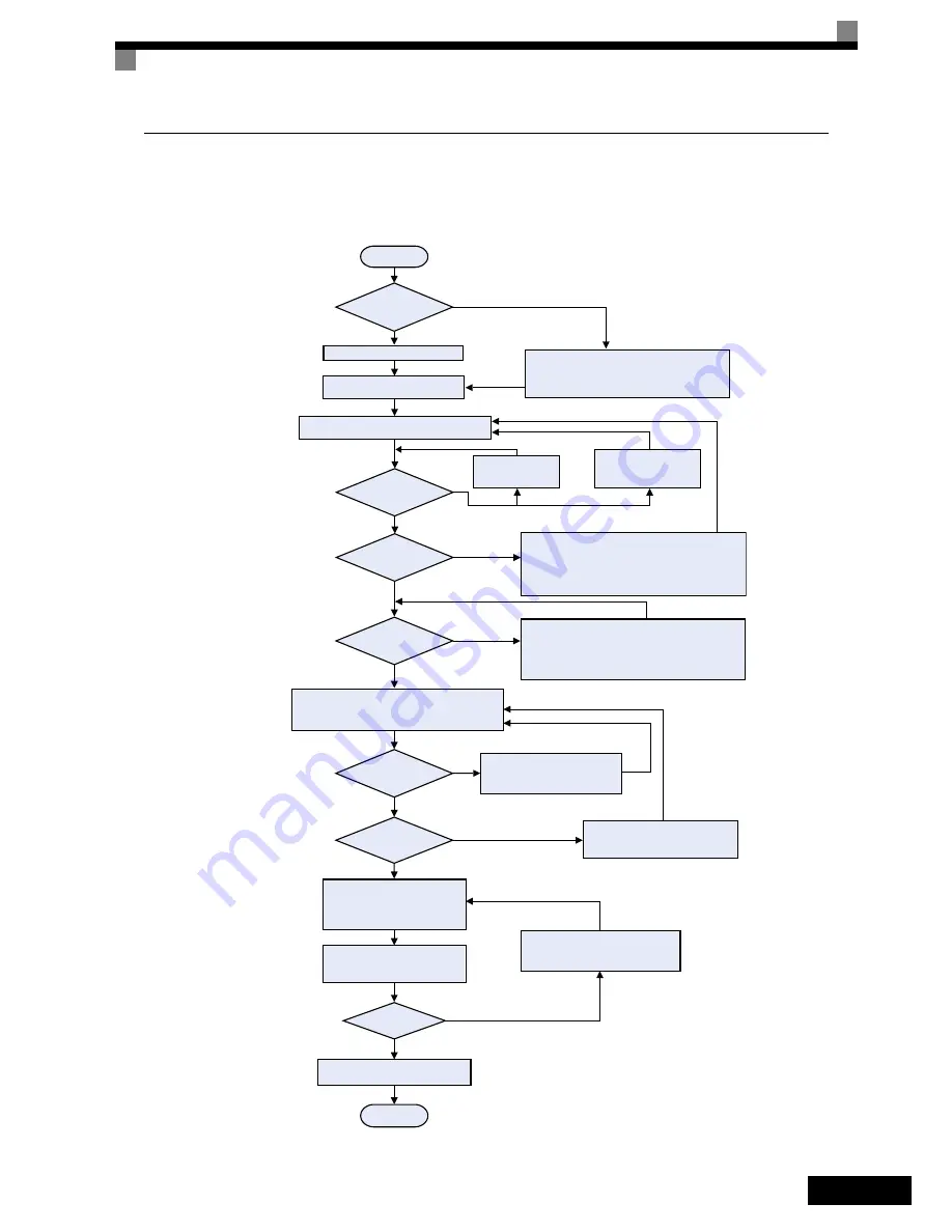
 shows the autotuning procedure for an encoder offset tuning. The procedure should be performed if the 

encoder has been changed or has not been aligned correctly. Before tuning make sure that PM losed loop vec-
tor control is selected (A1-02 = 6) and that the E1-

††

 and E5-

††

 parameters are set up correctly.

Fig 8  Encoder Offset Autotuning

* Check the wiring
* Check/readjust the encoder
   power supply

Yes

* Check the encoder wiring
* Change parameter F1-05

START

Remove the ropes.

Does PGO (no 

encoder feedback)

occur?

Set the Base Block inputs BB and BB1

Open the brake, close the motor contactor,

turn the motor slowly in Forward direction*

1

 and check 

monitor U1-05.

Is the sign of the

U1-05 value positive 

(not -)?

No

Yes

No

Yes

Set:

T1-01 = 4 - Encoder Offset Tuning

Press the UP button until the “Tuning

Ready” display appears.

Close the motor contactor(s) and 

press the RUN key.

Wait until the tuning is finished.

Tuning successful?

No
(Fault code is 
displayed)

Yes

(”Tuning successful”

display is shown)

  Refer to

and eliminate the fault source.

Open the contactors, open the base

block inputs and close the brake

FINISH

Is it possible to remove 

the ropes ?

Does a CPF24 fault

occur?

Balance the car so that it does not move

with open brakes.

Note: The tuning accuracy will be lower

in this tuning mode

* Check parameter n8-35
* If EnDat / Hiperface is used
   -  check the encoder power supply
   -  check the CLOCK and DATA signal wiring
* Switch off the power supply.

No

No

Yes

Does a OPE06 fault

occur?

Check parameter

 * F1-01

* n8-35

Switch off the power supply 

and check if PG card is

correctly installed

Yes

No

Does a OPE02 fault

occur?

* Check if the correct PG constant (F1-01) and
   absolute encoder resolution (F1-21) has been set.
* Refer to:

   and eliminate the fault source

No

Yes

Switch ON the power supply if it is OFF

page 27, Auto-tuning Faults

page 26, Operator Programming Errors (OPE)

* 1. Forward direction means: 

The direction the motor turns with an UP command at terminal S1 (i.e. 

with a clockwise rotating 3 phase supply and U-U, V-V, W-W wiring 

between inverter and motor). Usually the direction is clockwise seen 

from the motor shaft (traction sheave) side.

Refer to the motor instruction manual or consult the manufacturer for 

details about the rotation direction.

Summary of Contents for L7Z -

Page 1: ...Quick Start Guide L7Z Cat No I62E EN 01...

Page 2: ......

Page 3: ...n 13 Autotuning 14 Autotuning Mode Selection 14 Autotuning Alarms and Faults 15 Autotuning Procedure with Induction Motors 16 Autotuning Procedure for PM Motors 17 PM Motor Encoder Offset Tuning 18 Ri...

Page 4: ...RC interference suppression filters capacitors or overvoltage protection devices to the inverter input or output To avoid unnecessary over current faults etc being displayed the signaling contacts of...

Page 5: ...unauthorized persons must not be allowed access to these inverters Keep these Safety Precautions and Instructions for Use readily accessible and supply them to all persons with any form of access to t...

Page 6: ...is L7 inverter can drive induction motors as well as permanent magnet motors Always select the appropriate control mode For induction motors use V f Open Loop Vector or Closed Loop Vector control A1 0...

Page 7: ...dance grounding of HF interference The use of grounding straps instead of cables is therefore definitely advisable Moreover cable shields must be connected with purpose made ground clips 3 Laying Cabl...

Page 8: ...location without excessive oscillation Install the Inverter in a location free from chlorides Install the Inverter in a location free from direct sunlight Installation Orientation Install the Inverter...

Page 9: ...ter input or a DC reac tor at the DC reactor connection terminals Use a surge absorber or diode for inductive loads near the Inverter Inductive loads include magnetic con tactors electromagnetic relay...

Page 10: ...d ground Cable shields have to be grounded on both cable ends Main Circuit Terminals Main circuit terminal functions are summarized according to terminal symbols in Table 1 Wire the terminals correctl...

Page 11: ...ly for analog references 15 V Max current 20 mA A1 Frequency reference 0 to 10 V 100 0 to 10 V 20 k AC Analog reference neutral E G Shield wire optional ground line connection point Dig ital output si...

Page 12: ...S2 SC IP24V 24V CN5 A1 A3 B1 B3 B2 A2 External Power Supply Sinking Mode NPN S1 S2 SC IP24V 24V CN5 A1 A3 B1 B3 B2 A2 24 VDC Internal Power Supply Sourcing Mode PNP S1 S2 SC IP24V 24V CN5 A1 A3 B1 B3...

Page 13: ...ax 1A 30VDC max 1A M1 M2 M3 M5 M4 M6 Brake Command Factory setting Contactor Control Factory setting Inverter Ready Factory setting Multi function contact output 250VAC max 1A 30VDC max 1A Analog inpu...

Page 14: ...ent Key Selects menu items sets parameter numbers and decrements set values Used to move to the previous item or data DATA ENTER Key Enters menus and parameters and set validates parameter changes RUN...

Page 15: ...rce Analog Input Digital operator b1 02 0 Set up the analog digital I O s in the H1 xx H2 xx and H3 xx parameters Set up the Acceleration Deceleration times C1 xx S Curves Jerk C2 x Make test runs Fin...

Page 16: ...ode Selection As the first thing after power up one of the four control modes must be selected depending on the machine type The Closed Loop Vector modes require PG feedback cards Table 4 shows the re...

Page 17: ...p value E2 02 and the no load current E2 03 after the first run with nominal speed Autotuning for Line to Line Resistance T1 01 2 Non rotating autotuning for line to line resistance can be used in V f...

Page 18: ...tors have to be closed 5 For autotuning the BB and BB1 signals must be ON Inverter must not be in base block condition 6 Confirm that the motor is mechanically fixed and can not move 7 Power is suppli...

Page 19: ...02 2 3 Yes Enter auto tuning mode and set parameter T1 01 2 Set T1 02 Motor rated power T1 04 Motor rated current Press the UP button until Tuning Ready display appears Set T1 02 Motor rated power T1...

Page 20: ...wer supply if it is OFF Check parameter n8 35 If EnDat Hiperface is used check the encoder power supply check the CLOCK and DATA signal wiring Switch off the power supply No Yes Does a OPE06 fault occ...

Page 21: ...nd eliminate the fault source Open the contactors open the base block inputs and close the brake FINISH Is it possible to remove the ropes Does a CPF24 fault occur Balance the car so that it does not...

Page 22: ...Source Selection The speed reference source can be selected using parameter b1 01 The factory setting is the digital operator b1 01 0 i e the speeds can be selected using digital inputs Speed Selecti...

Page 23: ...ut the inverter decelerates to the leveling speed d1 17 when the selected speed signal is removed Inspection Speed can not be selected as travel speed To select the leveling speed as travel speed the...

Page 24: ...f d1 18 is set to 2 and no digital input is set to nominal speed selection the speed reference with speed selection input set is nominal speed d1 09 When the leveling speed signal is set the inverter...

Page 25: ...eleration time n5 05 must be tuned Motor Acceleration Time Auto Tuning n5 05 Before the n5 02 auto tuning is performed the motor data autotuning and the general setup should have been finished Do the...

Page 26: ...Increase the gain to improve the responsiveness to the speed reference Decrease the gain if vibrations or oscillations occur 1 The order of giving the UP or DOWN command has no influence 2 n5 01 shoul...

Page 27: ...04 0 1 or 2 and A1 02 3 or 6 The speed deviation is higher than the F1 10 value for the time F1 11 or longer Reduce the load Lengthen the acceleration time and deceleration time Check the mechanical s...

Page 28: ...rent exceeded the motor over load curve The overload curve is adjustable using parameter E2 01 Motor Rated Current L1 01 Motor Protection Selection and L2 02 Motor Protection Time Con stant Recheck th...

Page 29: ...eck the input voltage and the wiring of the input terminals Extend the settings in C1 01 03 05 07 Main Circuit MC Operation Failure No MC response during Inverter operation Replace the Inverter UV2 CT...

Page 30: ...too high or too low Closed Loop Vector for PM only Check the motor wiring Check the motor rated current input value Reduce or increase the current level for leakage inductance tuning by changing para...

Page 31: ...al P gain 2 Set the proportional gain 2 and the inte gral time 2 of the speed control loop ASR for the minimum frequency The setting is active only for acceleration C5 04 ASR integral I time 2 C5 06 A...

Page 32: ...me Param Num Name Description n5 03 Feed forward proportional gain Speed reference response will increase as the setting of n5 03 is increased n5 05 Motor accelera tion time tuning 0 Disabled 1 Enable...

Page 33: ...Speed agree 1 Inverter ready 1 Minor fault 1 Major fault U2 13 Operation status at fault U2 14 Cumulative operation time at fault Fault History Data U3 01 to U3 04 Last fault to Fourth last fault U3...

Page 34: ...EN 31...

Reviews: