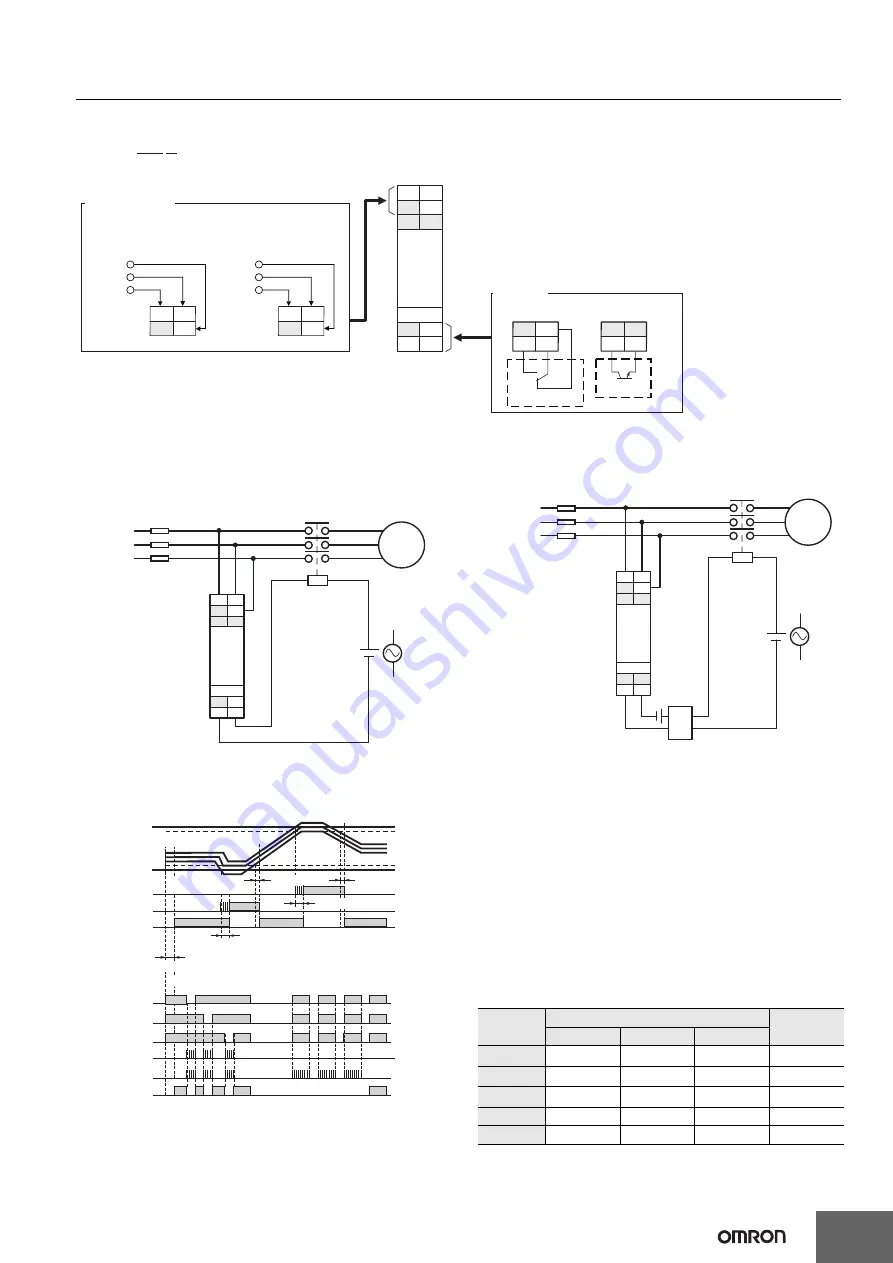
background image

K8DT-PM

3

Connections

Terminal Diagram

Note:

Do not connect anything to terminals that are shaded in gray.

Wiring Example

Relay Output

Transistor Output

Note:

Use copper wires with a rating of 75°C or an equivalent rating.

Timing Charts

Overvoltage/Undervoltage and Phase Sequence/Phase Loss Operation Diagram

Note: 1.

The K8DT-PM

@

 output contacts are normally operative.

2.

The power ON lock prevents unnecessary alarms from being 
generated during the unstable period when the power is first 
turned ON. There is no contact output during timer operation.

3.

Phase loss is detected by a drop in the L1, L2, or L3 voltage. 
A phase loss is detected when any of the phase-to-phase 
voltages goes below 60% of the rated input.

4.

L1 and L2 are also used for the power supply. If the voltage 
becomes very low, the Relay will not operate.

5.

Phase loss (on power supply side and load side) is not 
detected in the motor load during operation.

Operation Table

*1.

L1 and L2 are also used for the power supply. If the voltage 
becomes very low, the indicator will turn OFF.

*2.

The indicator will flash once per second after an incorrect phase 
is detected and once per 0.5 second during the detection time.

K8DT-PM1 C N

L1

14

L2

11

12

L3

DIP SW

Inside

Inside

(2) Output

C: Relay Output

T: Transistor Output

14

11

12

14

11

(1) Input Voltages

(1) (2)

3-phase, 
3 W
power 
supply

Phase-to-phase voltage:
 200 to 240 VAC

PM1

PM2

L1

L3

L2

3-phase, 
3 W
power 
supply

Phase-to-phase voltage:
 380 to 480 VAC

L1

L3

L2

3-phase 

voltage

Motor

Power 
supply 
AC/DC

L1

L2

L3

DIP SW

L1

14

L2

11

12

L3

PLC

Power
supply

AC/DC

3-phase 

voltage

Motor

L1

L2

L3

DIP SW

L1

14

L2

11

L3

L1

L3

L2

L3

L2

L1

Flashing

Flashing

L1

L2

L3

Phase sequence Operation

Phase Loss Operation

t: Operating time (0.1 to 30 s)

t: Operating time (0.1 to 30 s)

t1: Power ON lock (1 s)

t

t1

t

OVER_LED

UNDR_LED

Undervoltage

 set value

Power supply

voltage

Contacts 11-14 or 

transistor output

L1

L2

Input

L3

Hysteresis: 
Fixed at 5%

Hysteresis: Fixed at 5%

Lit

Flashing

Lit

Flashing

OVER_LED

Flashing

Flashing

L1

Input  L2

L3

UNDR_LED

Contacts 11-14 or 

transistor output

L2

L1

L3

Flashing

Delay time: 250 ms
(reference value)

Delay time: 250 ms
(reference value)

Item

Indicators

Contact 

operation

OUT_LED

OVER_LED

UNDR_LED

Normal

ON

OFF

OFF

ON

Overvoltage

OFF

ON

OFF

OFF

Undervoltage

OFF

OFF

ON

OFF

Phase Loss

OFF

Flashing 

*

1

Flashing 

*

1

OFF

Phase sequence

OFF

OFF

Flashing 

*

2

OFF

Summary of Contents for K8DT-PM

Page 1: ...h America Certification is pending for LR standards Models added with transistor outputs for superior contact reliability RoHS compliant Ordering Information Three phase Voltage and Phase sequence Pha...

Page 2: ...bient operating humidity 25 to 85 RH with no condensation Storage humidity 25 to 85 RH with no condensation Altitude 2 000 m max Applicable wires Stranded wires solid wires or ferrules Applicable wire...

Page 3: ...nd after an incorrect phase is detected and once per 0 5 second during the detection time K8DT PM1 C N L1 14 L2 11 12 L3 DIP SW Inside Inside 2 Output C Relay Output T Transistor Output 14 11 12 14 11...

Page 4: ...ck See Note Terminal block See Note Power indicator Output status indicator Overvoltage knob OVER Undervoltage knob UNDR Operating time knob T Alarm indicator 8 mm 8 mm Solid Wire 8 mm Stranded Wires...

Page 5: ...R The undervoltage can be set to between 30 and 30 of the rated input Turn the knob while there is an input to the input terminals until the alarm indicator flashes when the set value and the input ha...

Page 6: ...0 Three phase Voltage and Phase sequence Phase loss Relays K8DT PM1 K8DT PM2 Options Order Separately Front Cover Y92A D1A 52 7 3 5 1 8 17 5 5 85 DIN Tracks PFP 100N PFP 50N Dimensions in parentheses...

Page 7: ...rminals is 120 of the set value for overvoltage detection or 80 of the set value for undervoltage detection when the auxiliary relay in connection diagram 2 operates Close the switch and use a cycle c...

Page 8: ...tected because the motor terminal voltage does not drop very much even if a phase is lost when the load on the motor is light To detect motor load phase loss during operation use the undervoltage dete...

Page 9: ...alarm outputs may fail to operate This may result in physical damage to the facilities equipment or other devices that are connected to it To reduce this risk inspect the Relay regularly To maintain s...

Page 10: ...e terminal block may be damaged 25 Insert a flat blade screwdriver into the release holes at an angle The terminal block may be damaged if the screwdriver is inserted straight in 26 Do not allow the f...

Page 11: ...rom the release hole Checking Connections After the insertion pull gently on the wire to make sure that it will not come off and the wire is securely fastened to the terminal block To prevent short ci...

Page 12: ...maximum applied voltage for the clearance solid insulation and other factors There is basic insulation between the input terminals and output terminals Operating section must have reinforced or doubl...

Page 13: ...CONNECTED WITH THE PRODUCTS WHETHER SUCH CLAIM IS BASED IN CONTRACT WARRANTY NEGLIGENCE OR STRICT LIABILITY Further in no event shall liability of Omron Companies exceed the individual price of the Pr...

Page 14: ...IL 60169 U S A Tel 1 847 843 7900 Fax 1 847 843 7787 Regional Headquarters OMRON EUROPE B V Wegalaan 67 69 2132 JD Hoofddorp The Netherlands Tel 31 2356 81 300 Fax 31 2356 81 388 Contact www ia omron...

Reviews: