background image

Cat. No. N146-E1-02

Three-phase Phase-sequence Phase-loss Relay

 K8AB-PM

9

Checking Operation

Overvoltages

Gradually increase the input from 80% of the setting.
The input value will equal the operating value when the 
input exceeds the setting and the alarm indicator starts 
flashing. Operation can be checked by the relay output that 
will start after the operating time has passed.

Undervoltage

Gradually decrease the input from 120% of the setting and 
check the operation using the same method as for 
overvoltage.

Example: For monitoring mode set to three-phase three-wire 

monitoring, a rated voltage of 200 V, and an operating time 
of 5 s.

Note:

K8AB-PM

@

 output relays are normally operative.

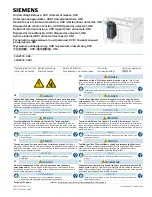
Connection Diagram 1

How to Measure the Operating Time

Overvoltage

Change the input suddenly from 0% to 120% of the set 
value and measure the time until the Unit operates.

Undervoltage

Change the input suddenly from 120% to 0% of the set 
value and measure the time until the Unit operates.

Operating Time

Adjust the slide resistor so that the voltage applied to the 
K8AB terminals is 120% of the set value (for overvoltage 
detection) and 80% of the set value (for undervoltage 
detection) when the auxiliary relay operates, as shown in 
connection diagram 2. Close the switch and use the cycle 
counter to measure the operating time.

Connection Diagram 2

Checking the Phase Sequence and Phase Loss 
Operation

Phase Sequence

Switch the wiring, as shown by the dotted lines in 
connection diagram 1, to reverse the phase sequence and 
check that the K8AB operates.

Phase loss

Create a phase loss for any input phase and check that the 
K8AB operates.

Operating Adjustment Knobs 

Use a screwdriver to turn the knobs. There is a stopper to 
prevent the knob from turning any further once it has been 
turned completely to the left or right. Do not force the knob 
past these limits.

Questions and Answers

Q

Operating set value

Input voltage

Alarm indicator

Relay output

Flashing

Lit

5 s

0 to 150 V

V1

Three-phase variable 
autotransformer

Overvoltage

Undervoltage

L1

L2

L3

3

φ

200 VAC

V2 V3

L1

L2

L3

Q

3

φ

, 200 VAC

L1

L2

L3

±

C 200 V

Cycle counter

V1

V2 V3

X

X/a

X/b

L1

L2

L3

R1

R2

R1:  Slide resistor
        200 

 200 W

R2:  100 

 400 W

Q

Q

Summary of Contents for K8AB-PM Series

Page 1: ...Legend 1 Basic Model K8AB Measuring and Monitoring Relays 2 Functions PM Three phase Phase sequence Phase loss Relay Simultaneous upper and lower monitoring 3 Rated Input Voltage 1 115 127 133 138 20...

Page 2: ...oss 0 1 s max Startup lock time LOCK 1 s or 5 s Switched using DIP switch Indicators Power PWR Green Relay output RY Yellow OVER UNDER Red Output relays Two SPDT relays NC operation Output relay ratin...

Page 3: ...time Fluctuation based on measured value at standard temperature 20 C to standard temperature 10 max Standard temperature to 60 C 10 max Humidity 25 to 80 Humidity influence Operating value Based on a...

Page 4: ...L1 L2 L3 T T Note 1 The K8AB PM output relay is normally operative 2 The power ON lock prevents unnecessary alarms from being generated during the instable period when the power is first turned on Th...

Page 5: ...or Terminal block See notes 1 and 2 Terminal block See notes 1 and 2 0 1 Item Meaning Power indicator PWR Green Lit when power is being supplied see note Relay status indicator RY Yellow Lit when rela...

Page 6: ...ch Settings The power ON lock time number of wires and rated voltage are set using the DIP switch located on the bottom of the Unit Load Voltage input Signal output 14 12 L1 L2 L3 11 L1 N L2 L3 Signal...

Page 7: ...urn the knob while there is an input to the input terminals until the alarm indicator flashes when the set value and the input have reached the same level Use this as a guide to set the voltage The ra...

Page 8: ...in accident or corruption of the product 3 Do not use thinner or similar solvent for cleaning Use commercial alcohol 4 When discarding properly dispose of the product as industrial waste 5 Only use th...

Page 9: ...just the slide resistor so that the voltage applied to the K8AB terminals is 120 of the set value for overvoltage detection and 80 of the set value for undervoltage detection when the auxiliary relay...

Page 10: ...operation As the graph shows phase loss cannot be detected because the motor terminal voltage does not drop very much even if a phase is lost when the load on the motor is light To detect motor load...

Page 11: ...Cat No N146 E1 02 Three phase Phase sequence Phase loss Relay K8AB PM 11...

Page 12: ...TIAL DAMAGES LOSS OF PROFITS OR COMMERCIAL LOSS IN ANY WAY CONNECTED WITH THE PRODUCTS WHETHER SUCH CLAIM IS BASED ON CONTRACT WARRANTY NEGLIGENCE OR STRICT LIABILITY In no event shall the responsibil...

Reviews: