background image

17 | 

P a g e

Setting up the Chart 

The first time the chart is loaded it is blank. To start graphing, first use the toolbar in the 
upper left of the chart to select which end devices to view. Next select which sensor type to 
view. The chart will now start to display the data. Up to two different sensor types can be 
selected. The first is plotted on the left axis and the second is plotted on the right axis. 

As End Devices are added to the chart they also appear in the key above the chart. Each 
measurement in the chart is displayed in a different color. The key displays the color followed 
by the End Device ID, the sensor number and the units of measure for each measurement. 
The sensor number is used to distinguish between sensors for units equipped with more than 
one sensor of the same type such as dual thermocouple inputs. 

Manipulating The Chart 

All chart axes are fully user customizable. By 
default, the cart will show one hour of data 
and scale each axis to fit the sensor 
readings received. The scale on each axis 
can be fixed to user defined extents and the 
amount of time shown can also be 
customized. 
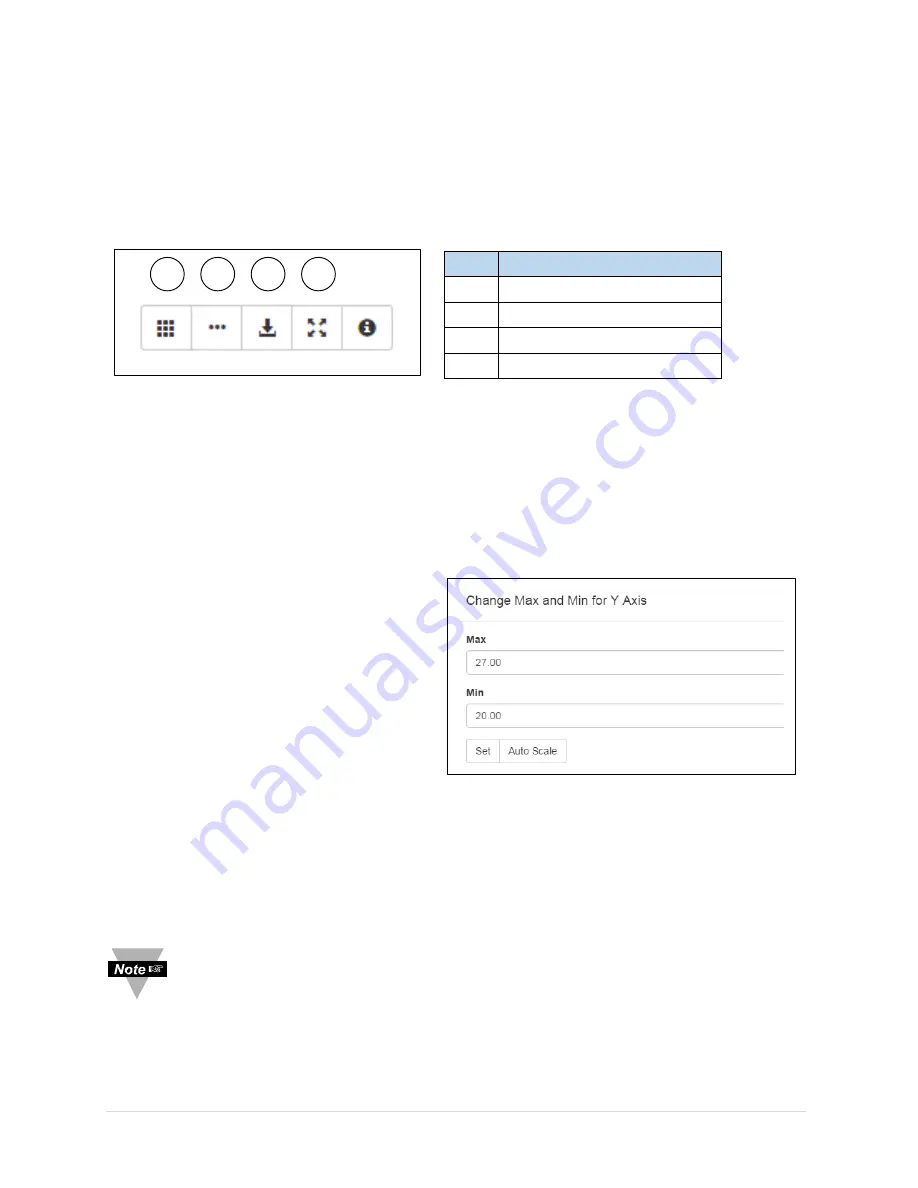
To change the scale of a vertical axis, click 
on the axis title, enter the desired 
Maximum and Minimum for the axis and 
press the 

Set

 button to change the scale. 

Use the 

Auto Scale

 button to have the chart 

scale to fit the data. 
To change the horizontal axis, enter the desired chart time, in minutes, into the time span box 
at the bottom of the chart. This indicated how much time the chart will cover. The chart 
always displays the most recent data. The frequency the chart is updated can also be 
changed. Enter the desired frequency in the update time box. 

Note:

 The update time for the chart is unrelated to the update time for End 

Devices. If the chart updates more often than the End Device, it will display the 
same data point multiple times. 

Item  Name 

Select End Devices 

Select Sensor Types 

Save Graph Data 

Reset Zoom 

2

1

3

4

Figure 11.   Chart Toolbar 

Figure 12.   Chart Axis Dialog 

Summary of Contents for ZW-REC

Page 1: ...e mail info omega com For latest product manuals www omegamanual info ZW REC zwSERIES WIRELESS RECEIVER TM Shop online at omega com User sGuide...

Page 2: ...pecifications without notice omega com info omega com Servicing North America U S A Omega Engineering Inc Headquarters Toll Free 1 800 826 6342 USA Canada only Customer Service 1 800 622 2378 USA Cana...

Page 3: ...10 3 3 CONNECTING TO THE ZW REC 10 3 4 DEFAULT PASSWORDS 11 3 5 NAVIGATING THE WEBPAGE 11 4 END DEVICE READINGS AND CONFIGURATION 12 4 1 END DEVICE READINGS PAGE 12 4 2 CHANGING END DEVICE SETTINGS 1...

Page 4: ...12 Figure 8 End Device Settings 13 Figure 9 End Device Status 15 Figure 10 Chart Page 16 Figure 11 Chart Toolbar 17 Figure 12 Chart Axis Dialog 17 Figure 13 System Information 18 Figure 14 Network Co...

Page 5: ...rsist Failure to follow all instructions and warnings may result in injury 1 2 Environmental and Operating Conditions The ZW REC is designed to be fixed mounted and operated in a clean and dry environ...

Page 6: ...shipping agent The carrier will not honor damage claims unless all shipping material is saved for inspection After examining and removing the contents save the packing material and carton in the event...

Page 7: ...an also wirelessly update firmware for compatible End Devices and Sensors The ZW REC is designed to require no software to setup and run A standard web browser can be used to monitor and chart all sen...

Page 8: ...Serial Number 3 USB Connector1 11 Network ID DIP Switches 4 Network Diagnostic LEDs 12 Network ID Label 5 Power Connector 13 MAC Address Label 6 Reset Button 14 IP Address Label 7 Ethernet Connector 1...

Page 9: ...rt NIDs 0 to 7 UW Series End Devices require a 5 digit NID referred to as a PAN ID for configuration The PAN ID corresponding to each NID is listed in Table 1 Consult the user manual of each specific...

Page 10: ...ning but this has no effect until the ZW REC is reset or power cycled Switch 3 is used to force DHCP on Changing Switch 3 to ON enables DHCP the next time the ZW REC is powered or reset Turning on DHC...

Page 11: ...Align the back of the unit over the three clips When engaged slide downward and snap the unit in place When mounting the unit be sure to leave room on the top for the Antenna and on the bottom and si...

Page 12: ...a default NID of 0 If this installation requires multiple Receivers ensure that each Receiver has a unique NID Record the NID on the Net Addr label on the back of the ZW REC for easy reference in the...

Page 13: ...ding Page Figure 6 is shown by default when logging into the ZW REC The page will initially have no entries End Devices are automatically added to the page as they are connected to the ZW REC The End...

Page 14: ...End Device Readings Page When logging into the ZW REC the End Device Readings page is displayed The readings page shows the current sensor data from all connected End Devices When an End Device turns...

Page 15: ...refer to the Sensor User Manual for sensor specific instructions General Settings The End Device Name can be up to 16 characters long Names are displayed on the web pages with the Device ID to help di...

Page 16: ...ntify mode The Clear End Device button removes the End Device from the ZW REC data base This will remove any Lost devices from the webpage and clear any errors If the Clear End Device button is presse...

Page 17: ...te between pages of End Devices End Devices can be selected and filtered in the same way as the reading page Name Description Type Model of End Device Sensors Number of Sensors Connected Power Current...

Page 18: ...n your needs Any combination of End Devices can be charted and two measurement types can be displayed at once Item Name Description 1 Toolbar Chart Utilities 2 Key Displayed Sensors 3 Axis 1 Axis for...

Page 19: ...efault the cart will show one hour of data and scale each axis to fit the sensor readings received The scale on each axis can be fixed to user defined extents and the amount of time shown can also be...

Page 20: ...or login is required for this page Changes to these settings could cause loss of connectivity to the webpages or the connected End Devices Care is advised when making any changes Some settings on this...

Page 21: ...vided Host Name DHPS and DNS Server The default host name for the ZW REC is zwrec where are the last 4 digits of the MAC Address See Figure 2 for the location of the MAC address The ZW REC can be acce...

Page 22: ...re to read data from the ZW REC using the ZW REC Serial Protocol detailed in the ZW REC Serial Programming Guide The default options work with the Omega Dashboard If different software is used these s...

Page 23: ...e Save button to save any changes Changes in this section take place immediately Note It is highly recommended to uncheck the Enable Energy Scan Box after the first boot up This allows End Devices to...

Page 24: ...to submit changes By default any password up to 16 characters long is allowed by the ZW REC If additional security is required check the require Strong Password box to enable the Strong Password Poli...

Page 25: ...ficate that is not issued by a Certificate Authority CA Most web browsers provide a warning page when connecting to the ZW REC indicating the SSL certificate is not issues by a trusted certificate aut...

Page 26: ...um Operating Temperature 0 to 70 C 32 to 158 F Humidity 90 RH non condensing Physical Properties Case Dimensions W x H x D 66 x 93 1 x 27 4mm Excluding Antenna Antenna Length 108mm Weight 90g Includin...

Page 27: ...the directives listed below and carries the CE marking accordingly The following CE Mark is affixed to this equipment The CE declaration is available at the website listed on the cover page of this m...

Page 28: ...that the website is authentic The ZW REC can automatically generate the required verification page The certificate issuer is allowed to remotely access to this page to verify the website To create a v...

Page 29: ...ll reduce the risk of dropped packets or network traffic interfering with the upgrade B 1 Upgrading from Version 1 X ZW REC units running version 1 X firmware require a multi part update to run versio...

Page 30: ...update is complete When the update has finished the Update Success screen in Figure 24 is shown Step 5 Connect to the ZW REC again using the IP Address recorded in Step 1 Follow the instruction in Se...

Page 31: ...In firmware update mode encryption is disabled so the IP address needs to start with http Step 3 Press the Browse button and select the firmware b64 file for the update Press the Upgrade button to upd...

Page 32: ...The Upload File button will now be usable Click the button to upload the firmware to the ZW REC The ZW REC will then update each selected End Device the next time it checks in The update process may...

Page 33: ...nels in North America and Europe If the Wi Fi channels currently in use are known select an 802 15 4 channel that does not overlap with it to reduce interference C 2 Signal Strength Indicator Signal S...

Page 34: ...When possible The ZW REC antenna should be parallel to the End Device antenna If the End Device does not have an external antenna the longest dimension of the End Device itself should be parallel to t...

Page 35: ...uipment generates uses and radiates radio frequency energy and if not installed and used in accordance with the instructions may cause harmful interference However there is no guarantee that interfere...

Page 36: ...aving a maximum gain of 2 2 dBi Antennas having a gain greater than 2 2 dBi are strictly prohibited for use with this device The required antenna impedance is 50 ohms D 2 CE Statement The following al...

Page 37: ...A if the unit is found to be defective it will be repaired or replaced at no charge OMEGA s WARRANTY does not apply to defects resulting from any action of the purchaser including but not limited to m...

Page 38: ...s M U Turbine Paddlewheel Systems M U Totalizers Batch Controllers pH CONDUCTIVITY M U pH Electrodes Testers Accessories M U Benchtop Laboratory Meters M U Controllers Calibrators Simulators Pumps M U...

Reviews: