TM
User’s Guide
Shop online
at
omega.com
e-mail: [email protected]
For latest product
manuals:
www.omegamanual.info
SS-015
-NA
L
ong Range
Wireles
s Process
and
Pulse
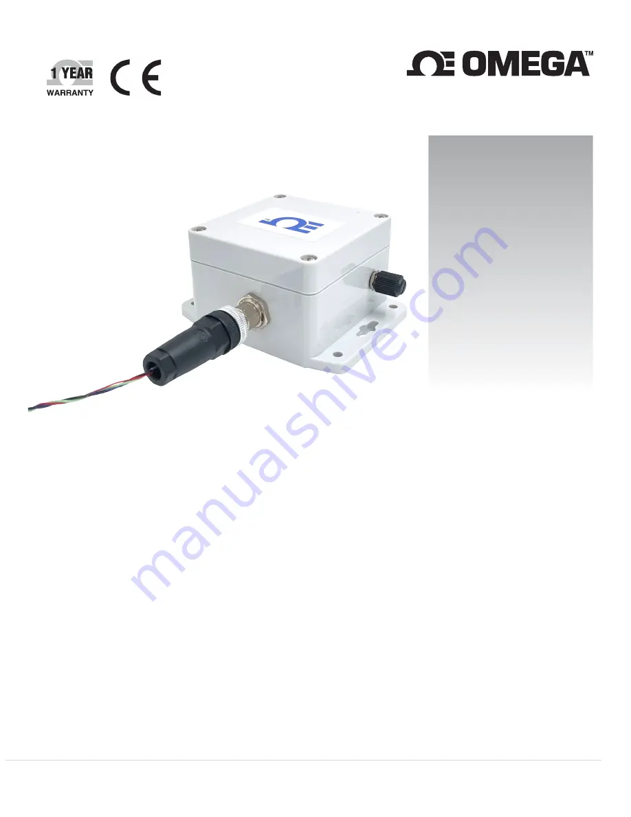
Input Smart Sensor
M12.5-S-M-FM screw terminal
adapter sold separately
1 |
P a g e
Page 1: ...online at omega com e mail info omega com For latest product manuals www omegamanual info SS 015 NA Long Range Wireless Process and Pulse Input Smart Sensor M12 5 S M FM screw terminal adapter sold s...
Page 2: ...er Service 1 800 622 2378 USA Canada only Engineering Service 1 800 872 9436 USA Canada only U S A Headquarters Tel 203 359 1660 e mail info omega com Fax 203 359 7700 The information contained in thi...
Page 3: ...e 16 6 3 3 2 Process Inputs Mixed Mode 17 6 3 4 Advanced Scaling 18 6 3 5 Setting an Alarm 19 6 4 Device Settings 20 6 4 1 Radio Control Low Power and High Power mode 20 7 Connecting to your Layer N G...
Page 4: ...ital Configuration Register 28 9 5 2 Digital Device Byte 29 9 5 3 Digital Sensor Parameters 29 9 5 4 Digital IPSO Definition 29 9 5 4 1 Digital Precision 29 9 5 4 2 Digital Sensor Trigger Function 30...
Page 5: ...it contains important information relating to safety and EMC Failure to follow all the safety precautions may result in injury and or damage to the equipment The following labels identify information...
Page 6: ...ary input or the pulse delay between the two signals The pulse totalizing function supports both standard counting and up down counting A mixed mode configuration option allows for the measurement of...
Page 7: ...ll batteries included Lifetime Up to 1 5 years with frequency of 1 reading per hour External Power 5VDC 1 75 W External power adapter optional External power specification based on Omega specific powe...
Page 8: ...en created and that a Layer N Gateway has been registered to that account Refer to the Layer N Gateway supporting documentation to complete this process Important If you are adding an SS 015 to a prev...
Page 9: ...r the Layer N Smart Interface that will be connected Note The connection type and parameters must be accurate for a proper connection to be established Failure to accurately set up communication param...
Page 10: ...in the below sections 6 3 1 Process Inputs Interface To configure the process inputs follow the steps below Figure 6 SYNC interface triple process Step 1 Click the Inputs configuration tab on SYNC an...
Page 11: ...nt Description DIN Digital Input 3 bit Binary Digital Input RATE Frequency Measure the frequency of rising edges WIDTH Pulse Width Measure the active time of a signal DUTY Duty Cycle Measure the of ac...
Page 12: ...Enable functionality which must be set HIGH to allow measurement The Digital Input DIN mode reports the binary value on the DIN pulse input pins Note the DIN inputs replace the functionality of the Pu...
Page 13: ...for the Up Counter when pulled up to 3 3 V If the Enable Input is Inactive it will pause stop the up counter until it is re enabled If the Enable Input is Active it will start the up count Activating...
Page 14: ...places the functionality of the Enable input The Reset and Direction input can be configured to be active high or active low See the Input Configuration Diagrams section for details PULSE RESET Counts...
Page 15: ...either have an internal 1 5k Pull Up PU or Pull Down PD and can be set to be either Active High or Active Low by selecting Normally Open NO or Normally Closed NC in the SYNC input configuration interf...
Page 16: ...to the wiring diagrams on page 8 6 3 3 1 Digital Inputs Mixed Mode The following table lists the available digital input configuration options available when in mixed mode Some options available in di...
Page 17: ...loop readings are rounded to the nearest 0 1 mA and voltage readings are rounded to the nearest 10 mV The process input is on pin 4 of the M12 5 pin connector when in mixed input mode 6 3 3 2 1 4 20...
Page 18: ...ng a new value in the Unit field and clicking Apply Settings This field is limited to a maximum of 4 characters Note that changing the Unit field does not change the base unit type only the display na...
Page 19: ...not transmit a notification can be set The option to enable Turn On an output can also be set The output chosen must not be currently used in a sensor mapping or ON OFF control module The data transm...
Page 20: ...Settings tab allows users to change between the default Low Power mode and the more power demanding High Power mode Low Power mode offers a range of up to 1 2 km depending on the environment High Pow...
Page 21: ...a green LED will blink periodically on the SS 015 each time data is transmitted to the Gateway Once the pairing process is complete replace the cover of the SS 015 and fasten the four screws securely...
Page 22: ...down the external power wait for 2 seconds and then attempt to repower the external device 9 2 Password Security Smart Sensor devices provide a password mechanism to ensure that log data cannot be ac...
Page 23: ...mV For example 4770 represents 4 770 volts This value is periodically updated by the internal SS 015 firmware 9 3 3 Status The Status register provides an indication of the battery status and results...
Page 24: ...sword Error Authentication Error and Probe Attached status bits are valid Legacy Smart Sensor devices SS 001 SS 002 have the Extended Valid bit clear indicating that the Password Fault Authentication...
Page 25: ...4 Sensor Interface Smart Probe devices share a common platform architecture that provides extensive monitoring and control capabilities through a set of platform generic registers These registers may...
Page 26: ...at Sensor Reading 9 4 2 Sensor Names Each sensor has a name The default names for the outputs are created based on the value being measured The default names may be overwritten such as Room_Temp or Ov...
Page 27: ...ent on the input range type selected The units of measure may be changed by the user Sensor Type Measurement SI Derived Units Measurement 0x18 DIN DIN DIN Digital Inputs 0x19 FREQUENCY RATE Hz RATE 0x...
Page 28: ...ULSE When configured for Mixed mode operation Digital pulse Process the DIN1 signal is used for the Process input signal The Pulse Delay and Up Down counter functions are not available 9 5 1 3 2 Lock...
Page 29: ...ATOR 2 0 V 9 5 3 Digital Sensor Parameters There are no Digital Sensor Parameters 9 5 4 Digital IPSO Definition The IPSO Digital definition provides signal range measured min max values IPSO object ty...
Page 30: ...of the channel and the signal types used 9 6 1 Process Descriptor Offset Name Value Description 0x00 Measurement Type 0x Analog Voltage and Current set by Sensor Type field in Configuration byte 0x01...
Page 31: ...r specified units of measure string 4 character maximum will be used in place of the default units of measure 9 6 1 3 3 Apply Scaling If set the user defined Offset and Gain values will be used to adj...
Page 32: ...1000 mV 0 2 Vdc 0 2000 mV 0x08bc Max Range 9 6 4 1 Process Precision The measured mA value is rounded to provide 0 1 mA resolution The measured mV value is rounded to provide 10 mV resolution 9 6 4 2...
Page 33: ...A if the unit is found to be defective it will be repaired or replaced at no charge OMEGA s WARRANTY does not apply to defects resulting from any action of the purchaser including but not limited to m...
Page 34: ...s M U Turbine Paddlewheel Systems M U Totalizers Batch Controllers pH CONDUCTIVITY M U pH Electrodes Testers Accessories M U Benchtop Laboratory Meters M U Controllers Calibrators Simulators Pumps M U...