


Model DFG-RS3 Digital Force/Torque Indicator
User’s Guide
10
6 SET POINT INDICATORS
6.1 General Information
Set points are useful for tolerance checking (pass/fail). Two limits, high and low, are specified and stored
in the non-volatile memory of the instrument and the primary reading is compared to these limits.
6.2 Configuration
To configure set points, select
Set Points
from the menu. The screen appears as follows:
Either one, two, or none of the set points may be enabled. To toggle between the tension and
compression (or clockwise and counter-clockwise) directions, press the
DIRECTION
key.
If two set points have been enabled, they are displayed in the upper left corner of the display. If only one
set point has been enabled, the word “OFF” appears in place of the value. If no set points have been
enabled, the upper left corner of the display will be blank.
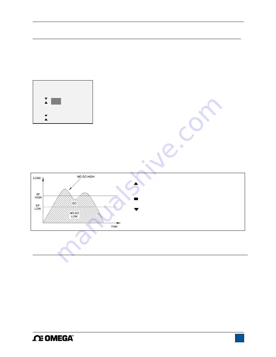
When set points are enabled, the following indicators are shown to the left of the primary reading:
– the displayed value is greater than the upper
load limit (NO GO HIGH)
– the displayed value is between the limits (GO)
– the displayed value is less than the lower load
limit (NO GO LOW)
Note:
Set point indicators reference the displayed reading, not necessarily the current live load.
7 OPERATING MODES
Caution!
In any operating mode, if the capacity of the instrument has been exceeded by more than 110%,
the display will show “OVER” to indicate an overload. A continuous audible tone will be sounded
(if beeps are enabled) until the MENU key has been pressed or the load has been reduced to a
safe level.
Three operating modes are possible with the DFG-RS3 indicator. To cycle between the modes, press
MODE
while in the home screen.
7.1 Real time (RT)
The primary reading corresponds to the live measured reading.
SET POINTS
Upper Disabled
* Upper Enabled
5.00
lbFin
Lower Disabled
* Lower Enabled
3.50 lbFin
Summary of Contents for DFG-RS3
Page 1: ...Model DFG RS3 Digital Force Torque Indicator...
Page 2: ...Model DFG RS3 Digital Force Torque Indicator User s Guide 1...
Page 22: ...Model DFG RS3 Digital Force Torque Indicator User s Guide 21 12 3 Dimensions IN MM...
Page 23: ...Model DFG RS3 Digital Force Torque Indicator User s Guide 22...
Page 24: ...Model DFG RS3 Digital Force Torque Indicator User s Guide 23 M 5250 1017...


