background image

Model DFG-RS3 Digital Force/Torque Indicator 


User’s Guide 


9


4.3 Menu navigation basics 

Most of the indicator’s various functions and parameters are configured through the main menu. To 
access the menu press 

MENU

. Use the 

UP

 and 

DOWN

 keys to scroll through the items. The current 

selection is denoted with clear text over a dark background. Press 

ENTER

 to select a menu item, then 

use 

UP

 and 

DOWN

 again to scroll through the sub-menus. Press 

ENTER

 again to select the sub-menu 

item.  
 
For parameters that may be either selected or deselected, press 

ENTER

 to toggle between selecting and 

deselecting. An asterisk (

*

) to the left of the parameter label is used to indicate when the parameter has 

been selected. 
 
For parameters requiring the input of a numerical value, use the 

UP

 and 

DOWN

 keys to increment or 

decrement the value. Press and hold either key to auto-increment at a gradually increasing rate. When 
the desired value has been reached, press 

ENTER

 to save the change and revert back to the sub-menu 

item, or press 

ESCAPE

 to revert back to the sub-menu item without saving. Press 

ESCAPE

 to revert one 

step back in the menu hierarchy until back into normal operating mode. 
 
Refer to the following sections for details about setting up particular functions and parameters. 
 

Note:

 As described above, the Plug & Test

TM

 smart connector retains all configuration and calibration 

data for the sensor, which includes menu settings. As such, a sensor must be connected in order for 
menu changes to be saved with that particular sensor. If a sensor is not connected and the 

MENU

 key is 

pressed, it is possible to browse through the menu parameters and make changes, but changes will not 
be saved. 


5   DIGITAL FILTERS 

 
Digital filters are provided to help smooth out the readings in situations where there is mechanical 
interference in the work area or test sample. These filters utilize the moving average technique in which 
consecutive readings are pushed through a buffer and the displayed reading is the average of the buffer 
contents. By varying the length of the buffer, a variable smoothing effect can be achieved. The selection 
of 1 will disable the filter since the average of a single value is the value itself.  
 
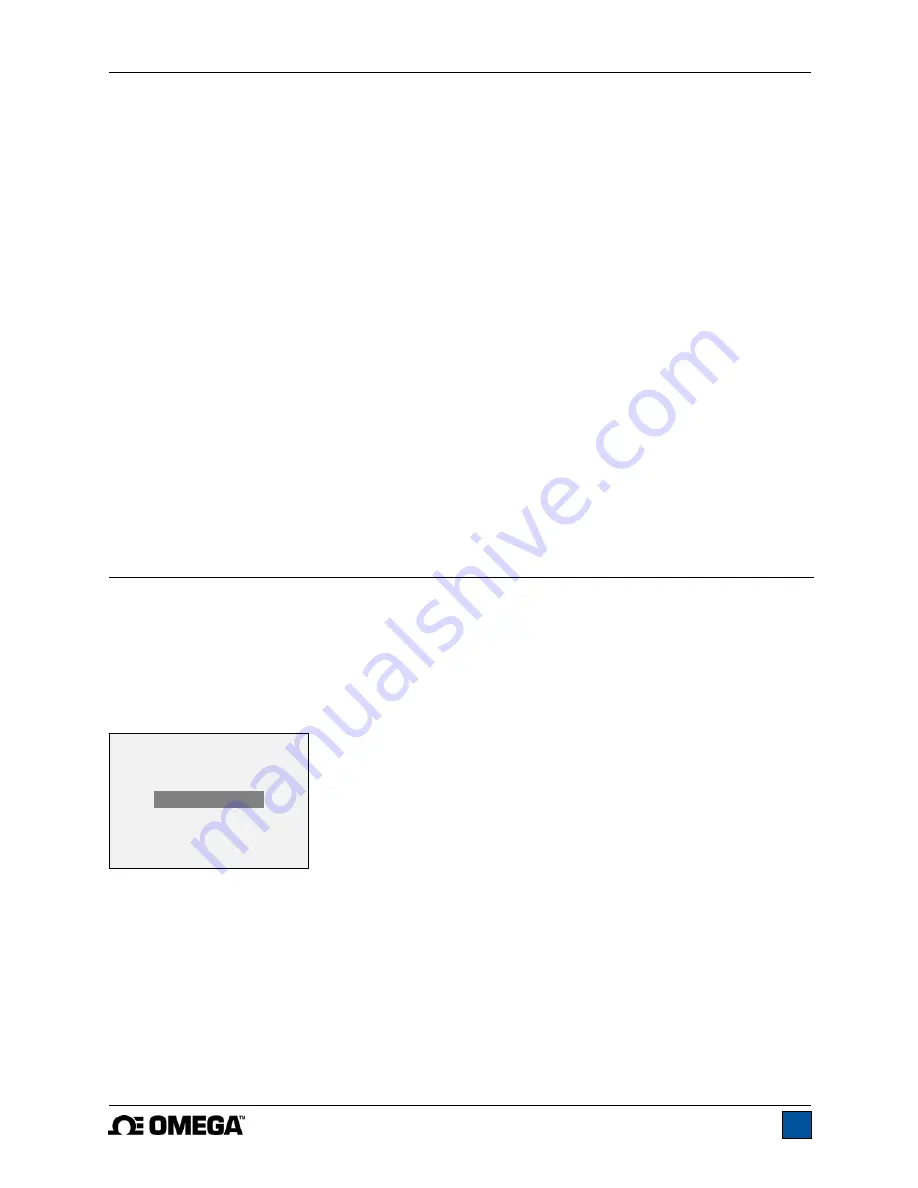
To access digital filter settings, select 

Filters

 from the menu. The display appears as follows: 


Two filters are available: 
 

Current Reading

 – Applies to the peak capture rate of the instrument.


Displayed Reading 

– Applies to the primary reading on the display.  

 
Available settings: 

1,2,4,8,16,32,64,128,256,512,1024. 

It is recommended to keep the current reading 

filter at its lowest value for best performance, and the displayed reading filter at its highest value for best 
stability. 
 

DIGITAL FILTERS 

(1 = Fastest) 


Current Reading 


      8 

        Displayed Reading 
                   1024 

Summary of Contents for DFG-RS3

Page 1: ...Model DFG RS3 Digital Force Torque Indicator...

Page 2: ...Model DFG RS3 Digital Force Torque Indicator User s Guide 1...

Page 3: ...provides setup safety and operation instructions Dimensions and specifications are also provided For additional information or answers to your questions please do not hesitate to contact us Our techn...

Page 4: ...indicator and connected to another without the need for re calibration or re configuration All such data is saved within a PCB located inside the smart connector The model number serial number and ca...

Page 5: ...connected to a DFG RS3 indicator Resolution information is shown in the sensors user s guide 1 4 Safety Proper Usage Read through the following safety instructions thoroughly before using the DFG RS3...

Page 6: ...f suitably rugged materials and components Similar precautions should be taken when mounting the sensor to a test stand work bench or other piece of equipment 2 POWER The DFG RS3 is powered either by...

Page 7: ...into place with a click Fig 3 1 Appropriate orientation of the connector To release the connector press both buttons on either side of the indicator housing to release the sensor as shown in Fig 3 2 b...

Page 8: ...Primary reading The current displayed load reading See Operating Modes section for details If a sensor is not plugged in this value will be replaced by a message as follows SENSOR NOT CONNECTED 4 Load...

Page 9: ...upper load limit the displayed value is between the load limits the displayed value is less than the lower load limit 9 Set points The programmed load limit values Typically used for pass fail type te...

Page 10: ...e As described above the Plug TestTM smart connector retains all configuration and calibration data for the sensor which includes menu settings As such a sensor must be connected in order for menu cha...

Page 11: ...corner of the display will be blank When set points are enabled the following indicators are shown to the left of the primary reading the displayed value is greater than the upper load limit NO GO HIG...

Page 12: ...selected 9 COMMUNICATIONS AND OUTPUTS Communication with the DFG RS3 is achieved through the micro USB port located along the left side of the housing as shown in the illustration in the Power section...

Page 13: ...ssion clockwise values have positive polarity tension counter clockwise values have negative polarity Numeric Only Output format includes the value only Polarity same as above Invert Polarity Compress...

Page 14: ...nsor can be calibrated at up to 10 points in each direction Enter the number of calibration points for each direction compression and tension or clockwise and counter clockwise At least one point must...

Page 15: ...quired Do not yet attach any weights or apply any calibration loads Press ENTER 6 The display appears as follows Optionally exercise the sensor several times at full scale if possible then press ENTER...

Page 16: ...F capacity sensor is calibrated and 5 data points were selected the load values will default to 10 20 30 40 and 50 lb Apply the calibration load Then press ENTER Repeat the above step for the number o...

Page 17: ...pter ensure that the output signal leads SG and SG have been installed into the appropriate terminal blocks Some sensor manufacturers consider SG to be a compression value while others consider it to...

Page 18: ...sed 11 2 Backlight There are several available initial settings applicable upon powering on the indicator To access these settings select Backlight from the menu The display appears as follows Selecti...

Page 19: ...functions for which audible tones will apply select Tones from the menu The screen appears as follows 11 5 Initial Mode This section is used to configure the initial mode upon powering on the indicat...

Page 20: ...nformation Welcome Screen The following screen is displayed at power up and can be accessed at any time by selecting Information from the menu RESTORE DEFAULT SETTINGS No Yes Digital Indicator Model D...

Page 21: ...0 of full scale display shows OVER at 110 and above Weight 0 7 lb 0 3 kg Included accessories Carrying case AC adapter battery USB cable resource CD USB driver and user s guide certificate of conforma...

Page 22: ...Model DFG RS3 Digital Force Torque Indicator User s Guide 21 12 3 Dimensions IN MM...

Page 23: ...Model DFG RS3 Digital Force Torque Indicator User s Guide 22...

Page 24: ...Model DFG RS3 Digital Force Torque Indicator User s Guide 23 M 5250 1017...

Reviews: