background image

Model DFG-RS3 Digital Force/Torque Indicator 


User’s Guide 


5


8.  Typical materials able to be tested include many manufactured items, such as springs, electronic 

components, fasteners, caps, films, mechanical assemblies, and many others. Items that should 
not be used with the sensor include potentially flammable substances or products, items that can 
shatter in an unsafe manner, and any other components that can present an exceedingly 
hazardous situation when acted upon by a force. Always wear eye and face protection when 
testing, especially in aforementioned hazardous cases. Extra bodily protection should be worn if a 
destructive failure of a test sample is possible. 
 

9.  In aforementioned hazardous situations, it is strongly recommended that a machine guarding 

system be employed to protect the operator and others in the vicinity from shards or debris. 


10.  Sensors have threaded holes or chucks, designed for the mounting of grips, fixtures, or 

attachments. If any such accessories are used, ensure they are mounted firmly to prevent a 
potential safety risk to the operator and others in the vicinity. If using an accessory from a supplier 
other than Omega, ensure that it is constructed of suitably rugged materials and components. 
Similar precautions should be taken when mounting the sensor to a test stand, work bench, or 
other piece of equipment. 


2   POWER 


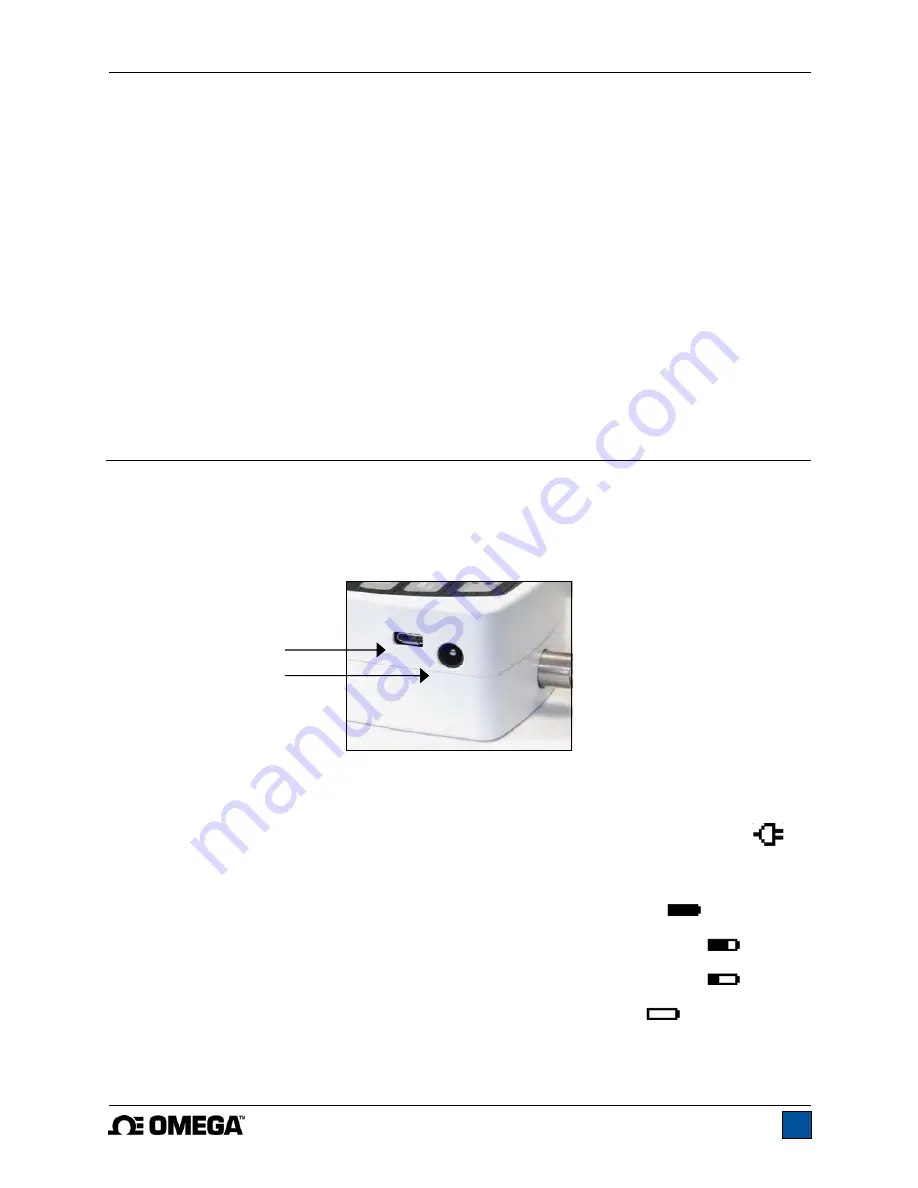
The DFG-RS3 is powered either by an 8.4V NiMH rechargeable battery or by an AC adapter. Since these 
batteries are subject to self discharge, it may be necessary to recharge the unit after a prolonged period 
of storage. Plug the accompanying charger into the AC outlet and insert the charger plug into the 
receptacle on the indicator (refer to the illustration below). The battery will fully charge in approximately 8 
hours.  


Caution!


Do not use chargers or batteries other than supplied or instrument damage may occur. 
 

If the AC adapter is plugged in, an icon appears in the lower left corner of the display, as follows: 


If the AC adapter is not plugged in, battery power drainage is denoted in a five-step process: 
 

1.  When battery life is greater than 75%, the following indicator is present: 


2.  When battery life is between 50% and 75%, the following indicator is present: 


3.  When battery life is between 25% and 50%, the following indicator is present: 


4.  When battery life is less than 25%, the following indicator is present: 


5.  When battery life drops to approximately 2%, the indicator from step 4 will be flashing. 

Several minutes after (timing depends on usage and whether the backlight is turned on or 

USB connector 

Power input jack 

Summary of Contents for DFG-RS3

Page 1: ...Model DFG RS3 Digital Force Torque Indicator...

Page 2: ...Model DFG RS3 Digital Force Torque Indicator User s Guide 1...

Page 3: ...provides setup safety and operation instructions Dimensions and specifications are also provided For additional information or answers to your questions please do not hesitate to contact us Our techn...

Page 4: ...indicator and connected to another without the need for re calibration or re configuration All such data is saved within a PCB located inside the smart connector The model number serial number and ca...

Page 5: ...connected to a DFG RS3 indicator Resolution information is shown in the sensors user s guide 1 4 Safety Proper Usage Read through the following safety instructions thoroughly before using the DFG RS3...

Page 6: ...f suitably rugged materials and components Similar precautions should be taken when mounting the sensor to a test stand work bench or other piece of equipment 2 POWER The DFG RS3 is powered either by...

Page 7: ...into place with a click Fig 3 1 Appropriate orientation of the connector To release the connector press both buttons on either side of the indicator housing to release the sensor as shown in Fig 3 2 b...

Page 8: ...Primary reading The current displayed load reading See Operating Modes section for details If a sensor is not plugged in this value will be replaced by a message as follows SENSOR NOT CONNECTED 4 Load...

Page 9: ...upper load limit the displayed value is between the load limits the displayed value is less than the lower load limit 9 Set points The programmed load limit values Typically used for pass fail type te...

Page 10: ...e As described above the Plug TestTM smart connector retains all configuration and calibration data for the sensor which includes menu settings As such a sensor must be connected in order for menu cha...

Page 11: ...corner of the display will be blank When set points are enabled the following indicators are shown to the left of the primary reading the displayed value is greater than the upper load limit NO GO HIG...

Page 12: ...selected 9 COMMUNICATIONS AND OUTPUTS Communication with the DFG RS3 is achieved through the micro USB port located along the left side of the housing as shown in the illustration in the Power section...

Page 13: ...ssion clockwise values have positive polarity tension counter clockwise values have negative polarity Numeric Only Output format includes the value only Polarity same as above Invert Polarity Compress...

Page 14: ...nsor can be calibrated at up to 10 points in each direction Enter the number of calibration points for each direction compression and tension or clockwise and counter clockwise At least one point must...

Page 15: ...quired Do not yet attach any weights or apply any calibration loads Press ENTER 6 The display appears as follows Optionally exercise the sensor several times at full scale if possible then press ENTER...

Page 16: ...F capacity sensor is calibrated and 5 data points were selected the load values will default to 10 20 30 40 and 50 lb Apply the calibration load Then press ENTER Repeat the above step for the number o...

Page 17: ...pter ensure that the output signal leads SG and SG have been installed into the appropriate terminal blocks Some sensor manufacturers consider SG to be a compression value while others consider it to...

Page 18: ...sed 11 2 Backlight There are several available initial settings applicable upon powering on the indicator To access these settings select Backlight from the menu The display appears as follows Selecti...

Page 19: ...functions for which audible tones will apply select Tones from the menu The screen appears as follows 11 5 Initial Mode This section is used to configure the initial mode upon powering on the indicat...

Page 20: ...nformation Welcome Screen The following screen is displayed at power up and can be accessed at any time by selecting Information from the menu RESTORE DEFAULT SETTINGS No Yes Digital Indicator Model D...

Page 21: ...0 of full scale display shows OVER at 110 and above Weight 0 7 lb 0 3 kg Included accessories Carrying case AC adapter battery USB cable resource CD USB driver and user s guide certificate of conforma...

Page 22: ...Model DFG RS3 Digital Force Torque Indicator User s Guide 21 12 3 Dimensions IN MM...

Page 23: ...Model DFG RS3 Digital Force Torque Indicator User s Guide 22...

Page 24: ...Model DFG RS3 Digital Force Torque Indicator User s Guide 23 M 5250 1017...

Reviews: