background image

Model DFG-RS3 Digital Force/Torque Indicator 


User’s Guide 


15


Apply a weight equal to the full scale of the instrument, then press 

ENTER

.  


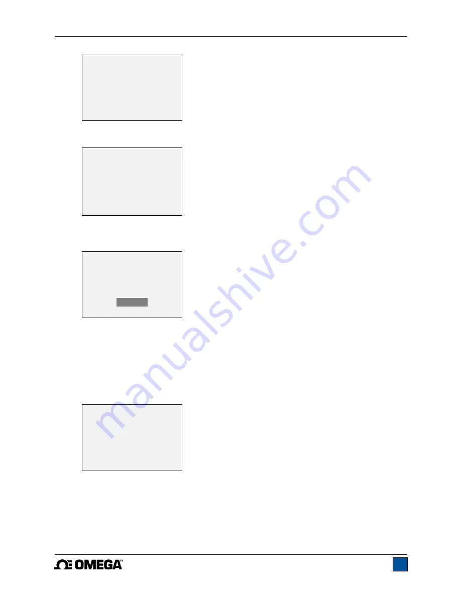
8.  After displaying “Please wait…” the display appears as follows: 


Remove the load applied in Step 8, leave the fixtures in place, then press 

ZERO


9.  The display appears as follows: 


Use the 

UP

 and 

DOWN

 keys to adjust the load value as required. The load values default to even 

increments, as indicated by the previously entered number of data points (even increments are 
recommended for best results). For example, if a 50 lbF capacity sensor is calibrated, and 5 data 
points were selected, the load values will default to 10, 20, 30, 40, and 50 lb. Apply the calibration 
load. Then press 

ENTER


Repeat the above step for the number of data points selected.  


10.  After all the compression calibration points have been completed, the display appears as follows: 


Press 

ENTER


11.  At the completion of the tension calibration, the display appears as follows: 

CALIBRATION 

COMPRESSION 

Gain adjust 

Apply full scale load 

10.000 lbF +/-20%, 

then press ENTER. 

CALIBRATION 

COMPRESSION 


Ensure no load,  

then press ZERO. 

CALIBRATION 

COMPRESSION COMPLETE 

       Reverse direction  
       for tension. 
       Attach necessary 
       weight fixtures, 
       then press ENTER. 

CALIBRATION 

COMPRESSION 

Apply load 

1 OF 5 

Enter load: 

2.000 lbF 

Press ENTER. 

Summary of Contents for DFG-RS3

Page 1: ...Model DFG RS3 Digital Force Torque Indicator...

Page 2: ...Model DFG RS3 Digital Force Torque Indicator User s Guide 1...

Page 3: ...provides setup safety and operation instructions Dimensions and specifications are also provided For additional information or answers to your questions please do not hesitate to contact us Our techn...

Page 4: ...indicator and connected to another without the need for re calibration or re configuration All such data is saved within a PCB located inside the smart connector The model number serial number and ca...

Page 5: ...connected to a DFG RS3 indicator Resolution information is shown in the sensors user s guide 1 4 Safety Proper Usage Read through the following safety instructions thoroughly before using the DFG RS3...

Page 6: ...f suitably rugged materials and components Similar precautions should be taken when mounting the sensor to a test stand work bench or other piece of equipment 2 POWER The DFG RS3 is powered either by...

Page 7: ...into place with a click Fig 3 1 Appropriate orientation of the connector To release the connector press both buttons on either side of the indicator housing to release the sensor as shown in Fig 3 2 b...

Page 8: ...Primary reading The current displayed load reading See Operating Modes section for details If a sensor is not plugged in this value will be replaced by a message as follows SENSOR NOT CONNECTED 4 Load...

Page 9: ...upper load limit the displayed value is between the load limits the displayed value is less than the lower load limit 9 Set points The programmed load limit values Typically used for pass fail type te...

Page 10: ...e As described above the Plug TestTM smart connector retains all configuration and calibration data for the sensor which includes menu settings As such a sensor must be connected in order for menu cha...

Page 11: ...corner of the display will be blank When set points are enabled the following indicators are shown to the left of the primary reading the displayed value is greater than the upper load limit NO GO HIG...

Page 12: ...selected 9 COMMUNICATIONS AND OUTPUTS Communication with the DFG RS3 is achieved through the micro USB port located along the left side of the housing as shown in the illustration in the Power section...

Page 13: ...ssion clockwise values have positive polarity tension counter clockwise values have negative polarity Numeric Only Output format includes the value only Polarity same as above Invert Polarity Compress...

Page 14: ...nsor can be calibrated at up to 10 points in each direction Enter the number of calibration points for each direction compression and tension or clockwise and counter clockwise At least one point must...

Page 15: ...quired Do not yet attach any weights or apply any calibration loads Press ENTER 6 The display appears as follows Optionally exercise the sensor several times at full scale if possible then press ENTER...

Page 16: ...F capacity sensor is calibrated and 5 data points were selected the load values will default to 10 20 30 40 and 50 lb Apply the calibration load Then press ENTER Repeat the above step for the number o...

Page 17: ...pter ensure that the output signal leads SG and SG have been installed into the appropriate terminal blocks Some sensor manufacturers consider SG to be a compression value while others consider it to...

Page 18: ...sed 11 2 Backlight There are several available initial settings applicable upon powering on the indicator To access these settings select Backlight from the menu The display appears as follows Selecti...

Page 19: ...functions for which audible tones will apply select Tones from the menu The screen appears as follows 11 5 Initial Mode This section is used to configure the initial mode upon powering on the indicat...

Page 20: ...nformation Welcome Screen The following screen is displayed at power up and can be accessed at any time by selecting Information from the menu RESTORE DEFAULT SETTINGS No Yes Digital Indicator Model D...

Page 21: ...0 of full scale display shows OVER at 110 and above Weight 0 7 lb 0 3 kg Included accessories Carrying case AC adapter battery USB cable resource CD USB driver and user s guide certificate of conforma...

Page 22: ...Model DFG RS3 Digital Force Torque Indicator User s Guide 21 12 3 Dimensions IN MM...

Page 23: ...Model DFG RS3 Digital Force Torque Indicator User s Guide 22...

Page 24: ...Model DFG RS3 Digital Force Torque Indicator User s Guide 23 M 5250 1017...

Reviews: